


-10-
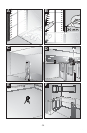
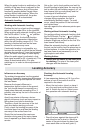
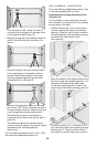
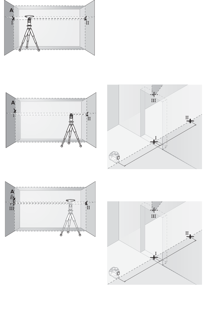
– Turn the tool by 180°, allow it to level in
and mark the cross point of the laser lines
on the opposite wall B (point II).
– Without turning the tool, position it close to
wall B. Switch the tool on and allow it to
level in.
– Align the height of the tool (using a tripod
or by underlaying, if required) in such a
manner that the cross point of the laser
lines is projected against the previously
marked point II on the wall B.
– Without changing the height, turn around
the tool by 180°. Direct it against the wall A
in such a manner that the vertical laser line
runs through the already marked point I.
Allow the tool to level in and mark the
cross point of the laser lines on the wall A
(point III).
– The difference d of both marked points I
and III on wall A results in the actual height
deviation of the tool alongside the
lateral axis.
On the measuring distance of 2 x 16ft = 32ft,
the maximum allowable deviation is:
32ft x ±0.0024in/ft = ±5/64 (0.078 in)
Thus, the difference d between points I and
III must not exceed 5/64 in (max.).
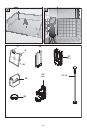
Checking the Leveling Accuracy of the
Vertical Line
For this check, a door opening is required
with at least 8 ft of space (on a firm surface)
to each side of the door.
– Position the tool on a firm, level surface
(not on a tripod) 8ft away from the door
opening. Allow the tool to level in while in
vertical operation with automatic leveling,
and direct the laser beam at the
door opening.
– Mark the center of the vertical laser line at
the floor of the door opening (point I), at a
distance of 8ft beyond the other side
of the door opening (point II) and at the
upper edge of the door opening (point III).
– Rotate the tool by 180° and position it on
the other side of the door opening directly
behind point II. Allow the tool to level in
and align the vertical laser line in such a
B
180˚
B
B
dd
180˚
8ft
8ft
8ft
8ft