


-11-
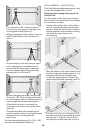
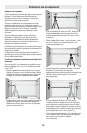
manner that its center runs exactly through
points I and II.
– Mark the center of the laser line at the
upper edge of the door opening as
point IV.
– The difference d of both marked points III
and IV results in the actual deviation of the
tool to the plumb line.
– Measure the height of the door opening.
The maximum admissible deviation is
calculated as follows:
Doubled height of the door
opening x 0.0024 in/ft
Example: For a door-opening height of 6.5ft,
the maximum deviation may be
2 x 6.5 ft x ±0.0024 in/ft = ±1/32 (0.312 in)
Consequently, points III and IV may be no
more than 1/32 in (max.) apart from
each other.
Working with the laser target plate
The laser target plate 15 increases the
visibility of the laser beam under unfavourable
conditions and at large distances.
The reflective part of the laser target plate 15
improves the visibility of the laser line. Thanks
to the transparent part, the laser line is also
visible from the back side of the laser
target plate.
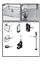
Working with the Tripod (Optional
Accessory)
A tripod offers a stable, height-adjustable
measuring support. Position thetool with the
1/4-20 tripod mount 10 onto the thread of the
tripod 21 or a commercially available camera
tripod. For fastening to a commercially
available construction tripod, use the 5/8-11
tripod mount 9. Tighten the tool with the
tripod mounting stud.
Fastening with the Universal Holder
(Accessory) (see figure D)
With the universal holder 19, you can fasten
the tool, e.g., to vertical surfaces, pipes or
magnetizable materials. The universal holder
is also suitable for use as a ground tripod
and makes the height adjustment of the
tool easier.
Working with the Measuring Plate
(Optional Accessory) (See figures A-B)
With the measuring plate 16, it is possible to
project the laser mark onto the floor or the
laser height onto a wall.
With the zero field and the scale, the offset or
drop to the required height can be measured
and projected at another location. This
eliminates the necessity of precisely adjusting
the tool to the height to be projected.
The measuring plate 16 has a reflective
coating that enhances the visibility of the
laser beam at greater distances or in intense
sunlight. The brightness intensification can
be seen only when viewing, parallel to the
laser beam, onto the measuring plate.
Working with the Laser Receiver
(Accessory) (see figure D)
Under unfavourable light conditions (bright
environment, direct sunlight) and for larger
distances, use the laser receiver for
improved finding of the laser lines 17. When
working with the laser receiver, switch the
pulse function on (see “Pulse Function”,
page 9).
Laser Viewing Glasses (Optional
Accessory)
The laser viewing glasses filter out the
ambient light. This makes the red light of the
laser appear brighter for the eyes.
• Do not use the laser viewing glasses as
safety goggles. The laser viewing glasses
are used for improved visualization of the
laser beam, but they do not protect against
laser radiation.
• Do not use the laser viewing glasses as
sun glasses or in traffic. The laser
viewing glasses do not afford complete UV
protection and reduce color perception.
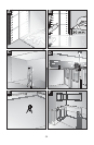
Work Examples (see figures C–H)
Applicational examples for the tool can be
found on the graphics pages.
Use with Attachments