


-10-
TO LOCK TRIGGER "ON": squeeze trigger,
depress button and release trigger.
TO UNLOCK THE TRIGGER: squeeze trigger
and release it without depressing the "Lock-
ON" button.
If the “Lock-ON” button is
continuously being depressed,
the trigger can not be released.
! %
The internal electronic feedback system
provides a "soft start", which will reduce the
stresses that occur from a high torque start.
The system also maintains the selected
speed under load for maximum efficiency.
"
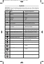
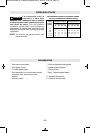
Maximum cutting efficiency can be obtained
by adjusting the blade orbit selector lever to
suit the material being cut.
The following chart will help you determine
which setting to use for your application. This
chart is intended as a guideline only, and test
cuts in scrap material should be performed
first to determine the best setting.
+::/4-
Hard materials such as
metals or thin sheet
metals. This setting can
be used with knife
blades, grit edge blades,
rasp work and down cutting blades.
+::/4-
Soft materials where
cleaner cutting or
delicate scrolling work is
performed.
+::/4-
Medium density
materials such as
harder woods or particle
board.
+::/4-
Soft materials such as
wood, plastics, etc. and
when fast cutting is
more important than a
clean cut.
#
Your jigsaw is equipped with a two position
chip blower to help keep the cutting line clear
of chips.
By adjusting the chip blower lever the force
of the discharge air may be altered as
follows;
##
For working with wood,
plastic and similar materials
that produce large amounts
of sawdust.
##
For working with metals
and when cooling agents
are used, or with dust
collection accessory.
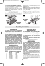
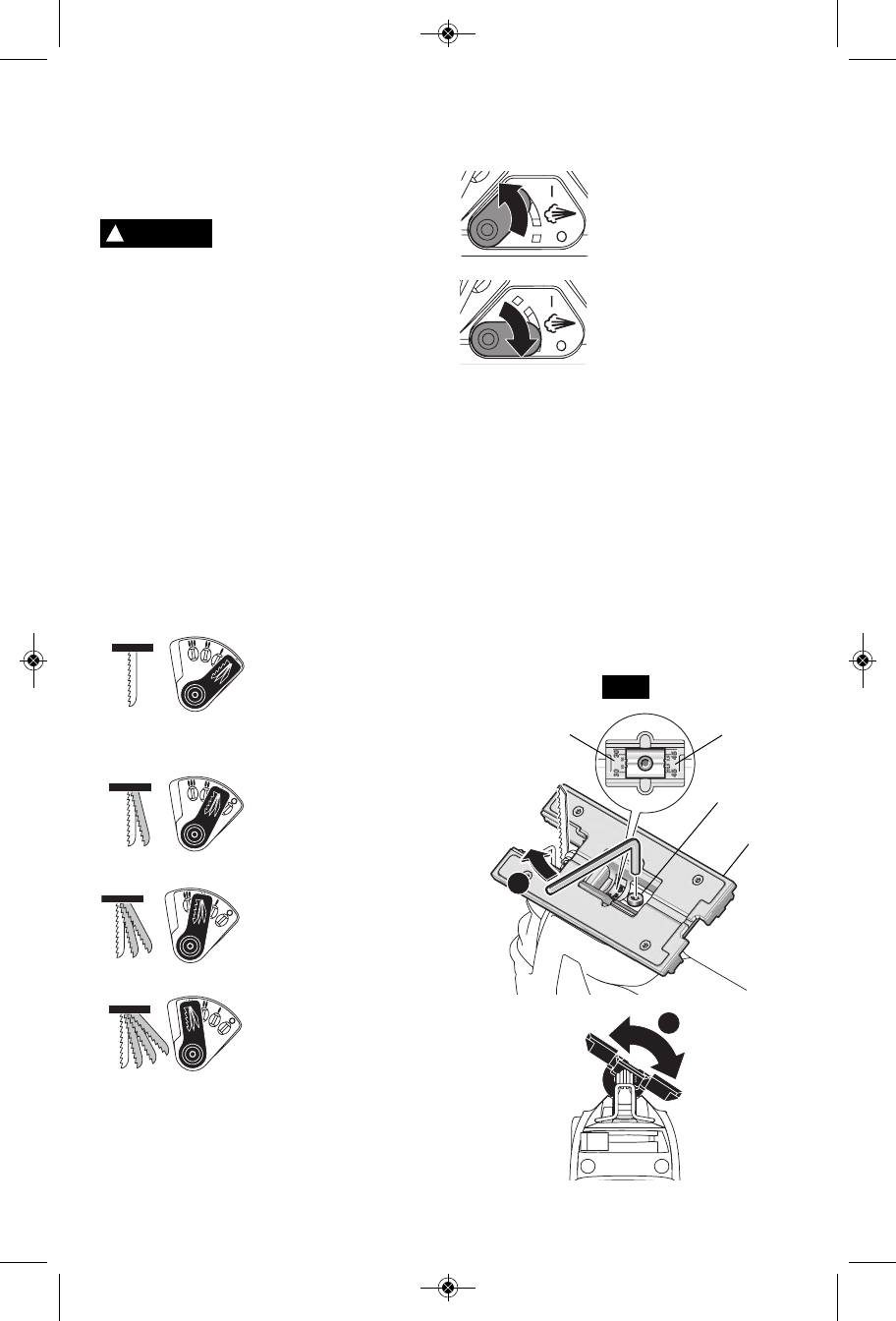
!
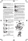
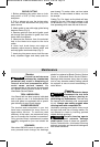
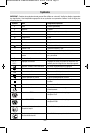
The footplate may be tilted to allow angle
cuts up to 45° in either direction (Fig. 6).
To adjust footplate, remove dust shroud if
used, loosen the footplate screw and slide
the footplate slightly forward towards the
back of tool, then rotate to desired angle
(Fig. 6).
The detent slots will hold the footplate firmly
at 0°, and there are additional position marks
for 15°, 22.5° 30° and 45° angles.
Intermediate angles may be set with a
protractor (Fig. 6).
After positioning the footplate, securely
tighten the footplate screw (Fig. 6).
!
WARNING
1
+/-
45°
2
BEVEL
SCALE
FOOTPLATE
SCREW
BEVEL
SCALE
FOOTPLATE
FIG. 6
BM 2610008439 06-10:BM 2610008439 06-10 6/16/10 2:59 PM Page 10