


!
The jigsaw cutting speed or stroke rate
required depends on the material being cut,
the type of blade being used, and the feed rate
preferred by the operator.
The best speed for a particular application is
largely determined by experience though as a
general rule, slower speeds are for denser
materials and faster speeds for softer materials.
Note that when the jigsaw is used at low speed
settings for an extended length of time, the
motor temperature will rise due to slower
speeds of the internal cooling fan. In such
cases, it is necessary to occasionally run the
tool at full speed for a few minutes to keep the
motor running at high efficiency.
"
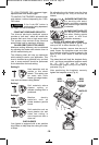
Your Jigsaw is equipped with a variable speed
dial. The blade stroke rate may be adjusted
during cutting operation by presetting the dial
on or between any one of the six numbers
(Fig. 5).
+::/4- 8':/4-9:851+96+83/4;:+
1 500 Max. 500
2 800 Max. 800
3 1400 Max. 1400
4 1900 Max. 1900
5 2400 Max. 2400
6 3100 Max. 3100
#
5*+2542?
The tool is switched “ON” by the switch button
located at the side of the motor housing. The
switch locks in the “ON” position, a
convenience for continuous operation (Fig. 1).
TO TURN THE TOOL “ON” slide the switch
button forward.
TO UNLOCK THE SWITCH, slide the switch
button backward.
"
#
5*+2542?
Your tool is equipped with a variable speed trigger
switch. The tool can be turned "ON" or "OFF" by
squeezing or releasing the trigger. The speed can
be adjusted from the minimum to maximum SPM
as set on the variable speed dial by the pressure
you apply to the trigger. Apply more pressure to
increase the speed and release pressure to
decrease speed.
Regardless of the pressure applied on the
trigger, the tool will not operate any faster than
maximum speed setting selected on the
variable speed dial.
! 5*+2542?
The "Lock-ON" button, located in the handle of
your tool allows for continuous operation at
maximum preset SPM without holding the
trigger (Fig. 1).
"
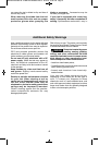
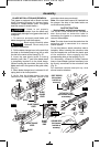
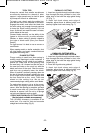
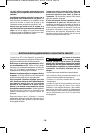
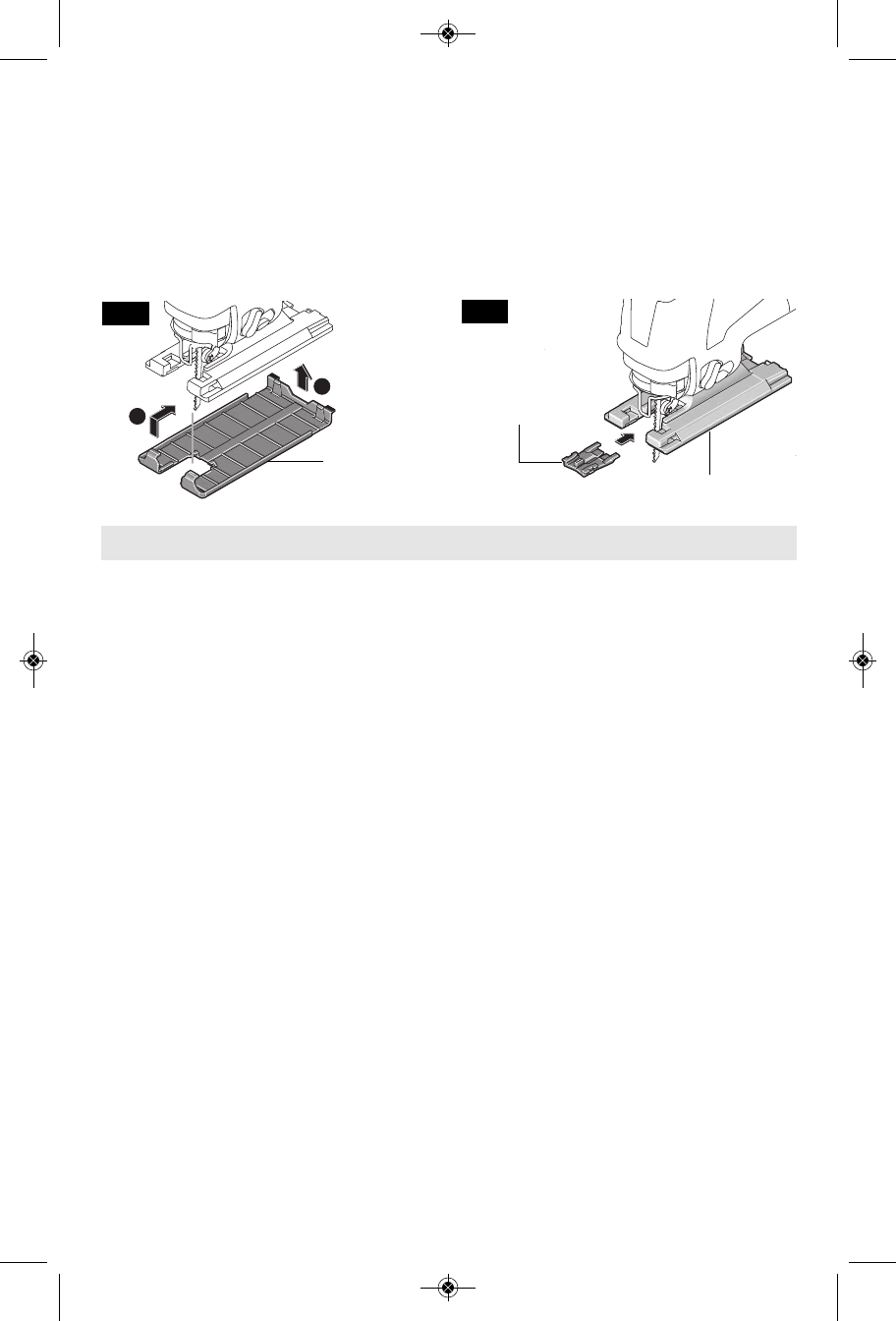
Your tool is equipped with a protective plastic
overshoe that protects finer surfaces.
To attach, hook overshoe over front of metal
footplate and snap into place at rear of
footplate (Fig. 4).
To minimize splintering of the top surface of
the material being cut, place the JA1008 anti-
splinter insert in the blade opening of the
footplate (Fig. 5).
5:+This insert will only work with blades that
have ground sides such as T301CD, T101B,
T101D, and T101DP.
5:+ When the insert is used with the non-
marring overshoe, the anti-splinter insert has
to be placed in overshoe.
-9-
1
2
ANTI-SPLINTER
INSERT
FOOTPLATE
NON-MARRING
OVERSHOE
FIG. 4
FIG. 5
6+8':/4-49:8;):/549
BM 2610008439 06-10:BM 2610008439 06-10 6/16/10 2:59 PM Page 9