


DP5UL 5 Speed Drill Press Assembly & Operating Instructions
10
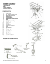
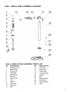
Column Assembly to Base
NOTE: Ideally, the base should be firmly bolted to the floor, prior to assembly of other components. The
mounting surface must be flat, level and capable of supporting the drill weight.
With the base on a flat level surface, bolt on the Column using the 4.M10 Hex head screws provided and
tighten. Carefully locate the table in its support and tighten up with the table locking handle. Check to
make sure the column securing set screws, at the column support, are tight. Fit the crank to the shaft on
the crank assembly.
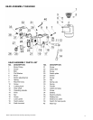
Head to Column
NOTE: It may be necessary to unscrew the Head Lock Set Screws slightly to make sure they do not
protrude internally as this would prevent the head from sliding fully into position. 1. Raise the head and
locate it on top of the column. 2. Align the head with the base and firmly secure with the set screws using
the wrench. Locate the three feed handles and screw them into the hub of the spindle feed shaft.
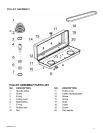
Pulley Cover Knob
Locate the knob, with pan head screw and attach to the cover, screwing on tightly.
Installing the Chuck
1. Slide the table up the column and secure it to within 6" of the spindle.
2. Open the jaws of the chuck to their maximum, using the chuck key supplied.
3. Put a piece of scrap wood on to the table to protect the chuck nose.
4. Make sure all parts are thoroughly clean, dry, and burr free.
5. Place the chuck over the end of the arbor and pull the spindle down using the feed handles.
Fitting the Drive Belts
Undo the Belt Tension Locking Screws (one on either side of the head) and turn the Belt Tension Lever
clockwise to bring the Motor Pulley closer to the Spindle Pulley (which will allow the belts to be slipped on
with ease).
Lightly grease the idler pulley pivot shaft and locate the idler pulley assembly in its' mounting between the
Motor and spindle Pulleys. Consult the chart inside the belt cover, and fit the belts in the position
corresponding to spindle/drill speed required.
Turn the Belt Tension Lever counter-clockwise so that tension is applied to the belts. Tension is correct
when the belts deflect by approx. 1/2" at their centers of run when using reasonable thumb pressure. Lock
the motor in the position with the Belt Tension Locking Screws. 1. The idler pulley will 'float' so that
tension is applied equally to both belts. 2. If the belt should slip while drilling, adjust the belt tension.