


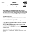
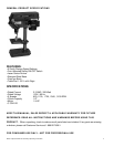

DP5UL 5 Speed Drill Press Assembly & Operating Instructions
11
SETTINGS AND ADJUSTMENTS
Table
The table may be raised, lowered or swivelled about the column, by loosening the table support locking
handle. Adjust accordingly using the table crank, and re-tighten the locking handle. If the table assembly
moves stiffly when being swivelled about the column, loosen the upper collar allen screw (at the rack) to
allow the collar to move very slightly, thereby providing a little more clearance between rack and collar.
Tighten the allen screw when satisfied. The table may also be turned on its axis by loosening the pinch
bolt at its' mounting shaft.
Spindle Depth
Located around the spindle feed shaft is a Depth Stop Collar, printed with a graduated scale. The collar is
capable of turning about the shaft and may be locked in place by the locking screw. The scale is printed in
both inches and metric. To set a drilling depth: 1. With the power OFF, lower the drill bit so that it contacts
the work, and hold in that position. 2. Loosen the locking screw and turn the collar so that the
measurement for the depth of hole required is in line with the pointer (C). Lock the collar in this position
using the locking screw. The drill is now set to drill holes to your predetermined depth, from that particular
start point.
Changing Drill Speed
Before changing the speed, make sure the machine is switched OFF, and unplugged. Undo the Belt
Tension Locking Screws on either side of the head and turn lever clockwise to relieve any tension on the
belts. Refer to the chart inside the belt cover install the belts in the positions corresponding to the spindle
speed required. Level the motor, on its bracket, away from the head, by turning lever counter clockwise so
that tension is applied to the belts.
NOTE: The idler pulley will 'float' so that tension is equally applied to both belts. Tension is correct when
the belts deflect by approx. 1/2" at their center when using reasonable thumb pressure. Lock the motor in
this position using the two locking screws. If the belt should slip while drilling, adjust the belt tension.
OPERATION
WEAR SAFETY EYEWEAR AND DUST FILTERS OR RESPIRATORS WHILE USING THIS TOOL.
lnsert the drill bit into the jaws of the chuck by approximately 1". Be certain that the jaws do not touch the
flutes of the drill. Before tightening the chuck, make sure that the drill bit is centered within the jaws. Make
sure the table height and position is set so that drill travel is sufficient for the job in hand.
Make sure the work is securely clamped, or held in a drill vise bolted to the table. Never hold it with bare
hands. Severe personal injury may be caused if the workpiece is forced out of the operator's hand, and
damage to the machine incurred if the work strikes the column. If the piece is of irregular shape and
cannot be laid flat on the table, it should be securely blocked and clamped. Any tilting, twisting or shifting,
results not only in a rough hole, but also increases drill bit breakage.
For small workpieces that cannot be clamped to the table, use a Drill Press Vise. The vise must be
clamped or bolted to the table. When drilling completely through wood, always position a piece of scrap
wood between the workpiece and the table to prevent splintering on the underside of the workpiece as the
drill breaks through. The scrap piece of wood must make contact with the left side of the column. In
addition, set the depth of drill travel so that the drill cannot possibly come into contact with the table, or,
align the table so that the center hole is directly in line with the drill bit. When completely satisfied that the
setup is sound, lower the Chuck Guard into place, and switch the machine ON.