


21 Sp
DG460300CK
Operation (Cont’d.)
If both hands are holding the saw,
they cannot be cut by the blade. Hold
the saw firmly to prevent loss of
control. NEVER place your hand ahead
of the saw blade since the saw could
jump forward over your hand.
Do not reach underneath the work. Do
not attempt to remove cut material
when blade is moving.
NEVER hold piece being cut in your
hands or across your leg. It is
important to support the work
properly to minimize body exposure,
blade binding, or loss of control.
Face the good side of the material down
and secure it in a bench vise or clamp it
down.
When following curves, cut slowly so the
blade can cut through cross grain. This
will give you an accurate cut and will
prevent the blade from wandering.
CAUSES AND USER PREVENTION
OF KICKBACK:
KICKBACK is a sudden reaction to a
pinched, bound or misaligned saw
blade, causing an uncontrolled saw to
lift up and out of the workpiece.
KICKBACK is the result of tool misuse
and/ or incorrect operating procedures
or conditions and can be avoided by
taking proper precautions as given
below:
1. Maintain a firm grip with both
hands on the saw and position your
body and arm to allow you to resist
KICKBACK forces. KICKBACK forces
can be controlled by the operator, if
proper precautions are taken.
2. When blade is binding, or when
interrupting a cut for any reason,
release the switch and hold the saw
motionless in the material until the
blade comes to a complete stop.
Never attempt to remove the saw
from the work or pull the saw
backward while the blade is in
motion or KICKBACK may occur.
Investigate and take corrective
actions to eliminate the cause of
blade binding.
3. When restarting a saw in the
workpiece, center the saw blade in
the kerf, or cut, and check that saw
teeth are not engaged into the
material. If saw blade is binding, it
may walk up or KICKBACK from the
workpiece as the saw is restarted.
4. Support large panels to minimize
the risk of blade pinching and
KICKBACK. Large panels tend to sag
under their own weight. Supports
must be placed under the panel on
both sides, near the line of cut and
near the edge of the panel.
5. Do not use dull or damaged blades.
Unsharpened or improperly set
blades produce narrow kerf causing
excessive friction, blade binding and
KICKBACK.
6. Base adjusting screws must be tight
and secure before making cut. If
blade adjustment shifts while
cutting, it may cause binding and
KICKBACK.
7. Use extra caution when making a
“Pocket Cut” into existing walls or
other blind areas. The protruding
blade may cut objects that can
cause KICKBACK.
8. Be cautious of pitchy, knotty, wet or
warped stock. These are most likely
to create pinching conditions and
possible KICKBACK.
9. Stay alert. Any distraction can cause
twisting or binding. Repetitive cuts
may lull the user into careless
movements.
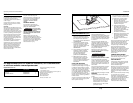
CUTTING WITH A STRAIGHTEDGE
Always use a rough cut blade when
possible. Clamp a straightedge on the
work parallel to the line of cut and
flush with the side of the saw base.
Either first mark the line of cut and
then position the straightedge parallel
and at the same distance as between
the blade and the side edge of the base
or first mark the side edge of the base
and then clamp the straightedge on
the mark and parallel to the cut line.
As you cut, keep the saw base edge
flush against the straightedge and flat
on the workpiece.
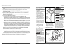
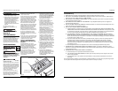
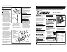
BASE ADJUSTMENT
Always be sure that the tool is switched
off. Unplug tool. The base can be
adjusted up to 45° by loosening the
base adjustment bolts on the underside
of the saw.
Align to the desired angle on
calibrated quadrant. Then tighten base
adjustment bolts (2). Because of the
increased amount of blade
engagement in the work and
decreased stability of the base, blade
binding may occur.
Keep the saw steady and the base
firmly on the workpiece.
BEVEL CUTTING
Always be sure
that the tool is
switched off and unplugged before
tilting the base.
With the base tilted, you can make
bevel cuts at any angle between 0° and
45° (left or right).
Loosen the bolts on the underside of
the tool with the allen wrench.
Tilt the base until the desired angle is
obtained. The edge of the motor
housing indicates the base angle by
graduations stamped on the base.
Tighten the 2 bolts to secure the base.
!
CAUTION
4
www.chpower.com
Operating Instructions and Parts Manual
Figure 3
Base Adjustment Bolts
Base flat at 0°
(dotted line)
Base angled
Para Ordenar Repuestos o Asistencia Técnica, Llame al Teléfono 1-800-424-8936
Sirvase darnos la siguiente información:
- Número del modelo
- Código impreso
- Descripción y número del repuesto
según la lista de repuestos
Descripción
Número del
Ctd.
Repuesto
Dirija toda la correspondencia a:
Campbell Hausfeld
Attn: Customer Service
100 Production Drive
Harrison, OH 45030 U.S.A.
Lista de Repuestos
Hoja de la sierra DG025800AV 1
Puerto para polvo DG028100AV 1
Llave Allen de 3mm DG026100AV 1