


FP2051, FP2052
1
2
7
13
3
4
5
6
8
9
10
11
12
30
14
15
16
17
18
19
20
47
21
20
21
19
23
24
25
27
27
28
29
31
32
33
34
35
43
37
38
39
40
42
41
44
45
46
54
51
48
50
49
53
52
36
26 Sp
Compresor de aire portátil
Sírvase darnos la siguiente información: Puede escribirnos a:
-Número del modelo Campbell Hausfeld / Attn: Parts Department
-Número de Serie (de haberlo) 100 Production Drive
-Descripción y número del repuesto según la lista de repuestos Harrison, OH 45030 U.S.A.
Para Ordenar Repuestos Sírvase Llamar al Distribuidor Más Cercano a su Domicilio
FP2051, FP2052
3
Installation (Continued)
Do not use a
grounding adapter with this product!
2. If repair or replacement of cord or plug
is necessary, do not connect grounding
wire to either flat blade terminal. The
wire with insulation having an external
surface that is green (with or without
yellow stripes) is the grounding wire.
Never connect
green (or green and
yellow) wire to a live terminal.
3. Check with a qualified electrician or
serviceman if grounding instructions
are not completely understood, or if in
doubt as to whether product is
properly grounded. Do not modify
plug provided; if it will not fit outlet,
have proper outlet installed by a
qualified electrician.
Overheating, short
circuiting and fire
damage will result from inadequate
wiring, etc.
WALL MOUNTING
This compressor can be mounted to the
wall for convenient storage. It can also
be operated while in the hanging
position.
Before mounting, select a location at a
wall stud or on a concrete surface.
Make sure that the mounting area
measures at least 24” x 30”.
Hang compressor on
a properly installed
hanger sturdy enough to support
compressor’s weight (approximately 25
pounds). Do not hang on peg board,
wallboard, or any structure not suited
to hold compressor’s weight.
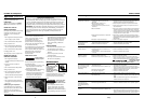
Mounting hanger bracket
For mounting to a wood stud, the
bracket has three holes in the center.
These holes are located in between the
two mounting hooks that attach to the
back of the compressor. Use a stud
finder to locate the center of the stud.
!
WARNING
!
CAUTION
!
WARNING
!
DANGER
Use the screws provided to attach the
bracket to the wall. Make sure to
mount to the wood stud, not just to
drywall.
For mounting to a concrete surface,
pre-drill holes in the concrete and insert
the anchors that are provided. Align
the holes in the bracket with the wall
anchors and use the three screws
provided to attach the bracket to the
wall.
Avoid mounting compressor to drywall
or gypsum board unless screws are
lagged into wood studs.
Mounting air compressor to bracket
There are three mounting hooks on the
wall hanging bracket. On the back of
the compressor shroud, there is an
opening that serves as a handle. The
two hooks on the top of the bracket fit
in the handle opening on the
compressor shroud. The remaining
hook on the bottom of the bracket fits
into the lower part of the compressor
shroud, below the handle opening.
HOSE STORAGE
1.Attach one of the threaded ends of
recoil hose to air outlet on front of
compressor.
2.Route recoil hose to side of tank
where hose strap is located.
3.Loosen lower end of hose strap.
4.Slide as much of recoil as possible
onto hose strap.
5.Reattach hose strap to compressor.
Operation
Definition of Terms
Regulator - The regulator controls the
amount of air pressure released at the
hose outlet.
ASME Safety Valve - This valve
automatically releases air if the tank
pressure exceeds the preset maximum.
Handle - Designed to move the
compressor.
Drain Valve - This valve is located on
the bottom of the tank. Use this valve
to drain moisture from the tank daily
to reduce the risk of corrosion.
Reduce tank pressure below 10 psi,
then drain moisture from tank daily to
avoid tank corrosion. Drain moisture
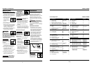
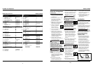
Gauge of Cord 18 18 16 14 14 12 12 10 10
Extension cords for 120V/2.5 Amp Unit
Length of Cord (ft) 25 50 100 150 200 250 300 400 500
www.chpower.com
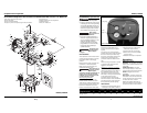
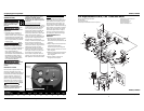
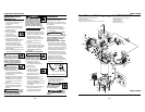
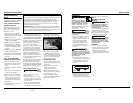
Figure 2 - Unit Identification
Tank gauge
Outlet
gauge
Safety valve
On/off switch
Regulator