


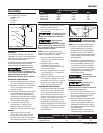

Gauge of Cord 16 14 10
Extension cords for 120V/10 Amp Unit
Length of Cord (ft) 25 50 100
HM7500
3
Assembly
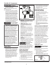
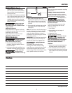
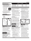
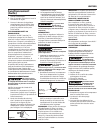
FOOT ASSEMBLY (FIGURE 1)
Foot assembly kit includes:
- 3 rubber feet
- 3 bolts
- 6 washers
- 3 nuts
Installation
LOCATION
It is extremely important to install the
compressor in a clean, well ventilated area
where the surrounding air temperature
will not be more than 100°F.
A minimum clearance of 18 inches between
the compressor and a wall is required
because objects could obstruct air flow.
Do not locate the
compressor air inlet
near steam, paint spray, sandblast areas
or any other source of contamination. This
debris will damage the motor.
Household use only. Store indoors.
ELECTRICAL INSTALLATION
1. Check and tighten all bolts, fittings,
etc., before operating compressor.
2. Operate compressor in a ventilated
area so that compressor may be
properly cooled.
3. Compressor should be located where
it can be directly plugged into an
outlet, but if this is not possible, an
extension cord may be used. It should
be selected using the extension cord
chart on page 3 as a guide.
4. To avoid loss of power and
overheating, it is better to use
additional air hose instead of
extension cords to reach work area.
WIRING
1. Local electrical wiring codes
differ from area to area. Source
wiring, plug and protector must
be rated for at least the amperage
and voltage indicated on motor
nameplate, and meet all electrical
codes for this minimum .
2. Use a slow blow fuse type T or a
circuit breaker.
Overheating, short
circuiting and fire
damage will result from inadequate
wiring, etc.
All wiring and
electrical
connections should be performed by a
qualified electrician. Installation must
be in accordance with local codes and
national electrical codes.
NOTE: 120 volt, compressor can be
operated on a 120 volt, 15 amp circuit
under the following conditions:
a. No other electrical appliances or
lights are connected to the same
branch circuit.
b. Voltage supply is normal.
c. Extension cords are of the
minimum gauge specified in this
instruction manual.
d. Circuit is equipped with a 15 amp
circuit breaker or a 15 amp slow
blow fuse type T.
3. If above conditions cannot be met
or if nuisance tripping of current
protection device occurs, it may be
necessary to operate compressor
from a 120 volt, 20 amp circuit.
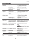
GROUNDING INSTRUCTIONS
1. This product should be grounded.
In the event of an electrical short
circuit, grounding reduces risk of
electrical shock by providing an
escape wire for electric current. This
product is equipped with a cord
having a grounding wire with an
appropriate grounding plug. Plug
must be plugged into an outlet that
is properly installed and grounded
in accordance with all local codes
and ordinances.
Improper use of
grounding plug can
result in a possible risk of electrical shock!
NOTE: Do not use grounding adapter.
2. If repair or replacement of cord or
plug is necessary, do not connect
grounding wire to either flat blade
terminal. The wire with insulation
having an outlet surface that is green
with or without yellow stripes is the
grounding wire.
3. Check with a qualified electrician or
serviceman if grounding instructions
are not completely understood, or
if in doubt as to whether product is
properly grounded. Do not modify
plug provided; if it will not fit outlet,
have proper outlet installed by a
qualified electrician.
Never connect
green (or green and
yellow) wire to a live terminal.
EXTENSION CORDS
To avoid loss of
power and
overheating, it is better to use
additional air hose instead of extension
cords to reach work area.
1. Use only a 3-wire extension cord
that has a 3-blade grounding plug,
and a 3-slot receptacle that will
accept plug on product.
2. Make sure extension cord is in good
condition, and heavy enough to
carry current product will draw. An
undersized cord will cause a drop in
line voltage resulting in loss of power
and overheating.
3. Table below shows correct size to
use depending on cord length and
Power cord White Line No
Motor cord White Load No
Power cord Black Line Yes
Motor cord Black Load Yes
✽ Wire and Terminal Guide
Wire Color Terminal Hot
(✽) When the unit is not in operation
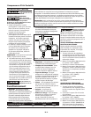
TEST
RESET
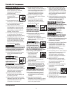
Figure 2 - Grounding Method
Grounding
Pin
Grounded
Outlet
www.chpower.com
Rubber Foot
Washer
Bolt
Washer
Nut
Figure 1 - Rubber foot installation