


4
Operating Instructions and Parts Manual
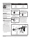
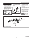
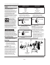
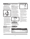
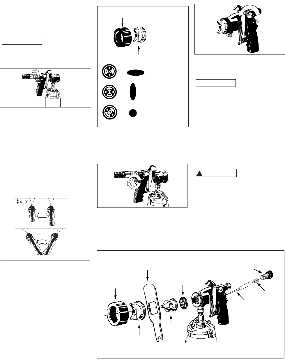
6. Attach the air hose quick-connect
fitting to the gun.
The quick-connect
NOTICE
fitting outer sleeve is
spring load ed and must be pulled back to
attach or remove it from the gun (See
Figure 10).
Figure 10 - Attaching The Air Hose
Operation
Always practice first. Make the gun
adjustments on a test surface such as
cardboard before spraying the project.
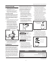
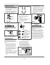
1. Keep the gun 4" - 9" from, and
parallel to the surface of the object
being sprayed. (See Figure 11). If
the material delivery is adjusted
for a small narrow pat tern, it may
be necessary to move as close as 2"
from the work surface.
Figure 11 - Painting Strokes
2. Move the gun in a smooth even
stroke. Begin the stroke before
pulling the trigger and continue the
stroke after releasing the trigger.
3. For best results overlap each stroke
by 25 to 50%.
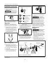
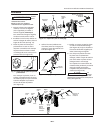
4. To adjust the spray pattern “type”,
turn the air cap to the desired
pattern position (See Figure 12).
Figure 12 - Adjusting The Spray
Patterns “Type”
5. To adjust the material flow, turn the
material control knob clockwise to
decrease and coun ter clock wise to
in crease. (See Figure 13).
Figure 13 - Adjusting The Material Flow
6. For fine pattern adjustment, turn
the air flow control knob clock wise
to de crease and counterclockwise to
in crease air flow (See Figure 14).
I
N
C
R
E
A
S
E
D
E
C
R
E
A
S
E
Figure 14 - Fine Pattern Adjustment
Reducing the air flow also reduces
overspray.
The turbine air
NOTICE
hose can be used to
blow-dry those areas that are too heavily
coated, or slow in drying.
The air from the turbine is warm as a
result of normal operation. This can
affect the finish quality on hot dry
days due to premature drying of some
coatings such as lacquer. Retarding
agents can be added to the material
to resolve this condition. Consult the
material supplier for the proper re tard-
ing agent, and mixing procedures.
Maintenance
CLEANING
Make sure the room
!
WARNING
is well ventilated
when using solvents. Dispose of all
materials properly, in ac cor dance with all
local reg u la tions.
1. Remove the material control knob,
spring, and nee dle. (Pull the trigger
to help remove the needle). NOTICE:
Removing the needle prior to
removing the nozzle will prevent
needle damage.
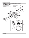
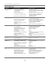
2. Using the sup plied wrench, un screw
and re move the re tain er ring, nozzle,
and airflow ring (See Figure 15).
I
N
C
R
E
A
S
E
Right
Wrong
=
=
=
Retaining
Ring
Spring
Horizontal Pattern
Use up and down
strokes
Vertical Pattern
Use right to left or
left to right strokes
Round Pattern
Stroke in any
direction
Figure 15 - Preparation For Cleaning
Retaining ring
Wrench
Air
Flow
Ring
Nozzle
Air Cap
Needle
Spring
Material Flow
Control Knob
Preparation (continued)
www.chpower.com