


3
VT6315, VT6358, VT6361
www.chpower.com
Operating Instructions
Introduction
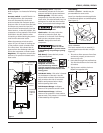
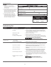
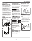
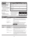
Refer to Figure 1 to locate the following
items.
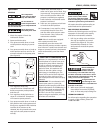
Pressure switch - Auto/Off Switch - In
the AUTO position, the compressor
shuts off automatically when tank
pressure reaches the maximum preset
pressure. After air is used from the tank
and drops to a preset low level, the
pressure switch automatically turns the
motor back on. In the OFF position, the
compressor will not operate. This switch
should be in the OFF position when
connecting or disconnecting the power
cord from the electrical outlet.
When the pressure switch turns the
motor off you will hear air leaking out
of the pressure switch unloader valve
for a short time. This releases the air
pressure from the discharge tube and
allows the compressor to restart easier.
Regulator - The regulator controls the
amount of air pressure released at the
hose outlet.
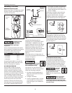
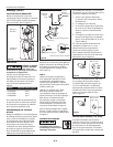
Assembly
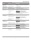
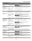
HANDLE ASSEMBLY - Handle may be
pre-assembled on some units.
Insert four handle screws through holes
in handle and tighten to tank baseplate
(See Figure 2).
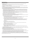
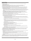
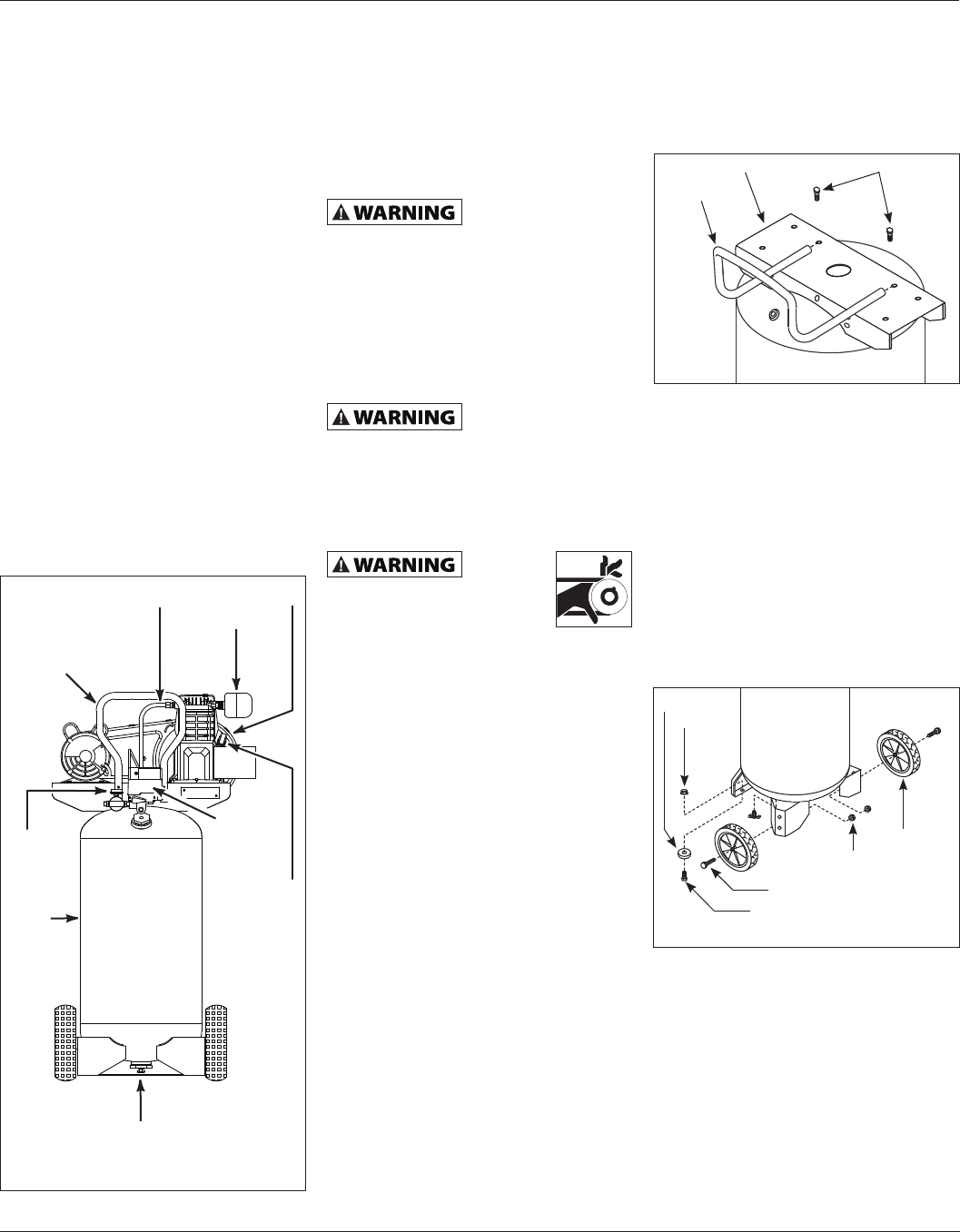
FOOT ASSEMBLY
The items marked with an asterisk (*)
were shipped loose with the unit (See
Figure 3).
1. Tilt unit to allow access to front foot
and secure properly to ensure unit
does not tip over.
2. Insert bolt through foot and bracket.
The foot should be on the lower side
of bracket.
3. Tightly secure with the lock nut.
Repeat on opposite side.
ASME Safety Valve - This valve
automatically releases air if the tank
pressure exceeds the preset maximum.
Discharge tube - This tube carries
compressed air from the pump to the
check valve. This tube becomes very hot
during use. To avoid the risk of severe
burns, never touch the discharge tube.
To avoid the risk of
severe burns, never
touch the discharge tube.
Check valve - One-way valve that
allows air to enter the tank, but
prevents air in the tank from flowing
back into the compressor pump.
Handle - Designed to move the
compressor.
Never use the
handle to lift the
unit completely off the ground. Handle
is intended only for pushing or pulling
product.
Belt Guard - Covers the belt, motor
pulley and flywheel.
Never
operate
compressor without a
beltguard. This unit can
start automatically without
warning. Personal injury or property
damage could occur from contact with
moving parts.
Tank Drain Valve - This valve is located
on the bottom of the tank. Use this
valve to drain moisture from the tank
daily to reduce the risk of corrosion.
Reduce tank pressure below 10 psi,
before opening drain valve.
Tank Pressure Gauge - Indicates
amount of air pressure stored in tank.
Hose Pressure Gauge - Indicates
amount of air pressure in hose used to
operate tools. This pressure is increased
or decreased by the regulator.
Drain
Petcock
Handle
Discharge Tube
Check Valve
Belt Guard
Tank
Breather/
Dipstick
& Oil Fill
Hole
Intake Filter
Hose
Pressure
Gauge
Pressure
Switch
Figure 1
Figure 2
Tank Baseplate Handle Screw
Handle
Figure 3
Foot*
Wheel*
Lock Nut*
Shoulder Bolt*
Nut*
Bolt*