


Page 7
For technical questions, please call 1-800-444-3353.
SKU 67501/68740
Assembly/Mounting
1.
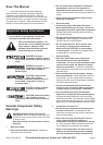
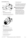
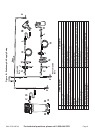
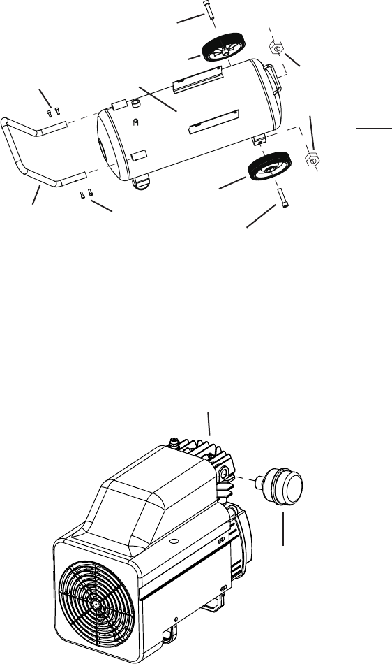
Figure 2
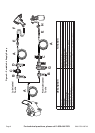
Bolt (64)
Bolt (64)
Hex
Nuts
(65)
Handle (72)
Bolts (71)
Bolts (71)
Tank (70)
Wheel (63)
Wheel (63)
Attach the Wheels (63) to the Tank (70),
using the Bolts (64) and Hex Nuts (65).
2. Slide the Handle (72) into the two slots on the top
of the Tank and secure in place with four Bolts (71).
3.
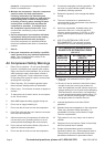
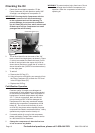
Figure 3
Air Filter
(6)
Cylinder Head (7)
Thread the Air Filter (6) onto the
side of the Cylinder Head (7).
4. Break in the new Air Compressor as follows:
a. Make sure the Power Lever is OFF and the
unit is unplugged. Insert a male coupler (sold
separately) into the female Quick Coupler (76)
and fully open all regulators and valves.
b. Plug in the Power Cord.
c. Turn the Power Lever ON.
d. Let the unit run for 30 minutes. Air will
expel freely through the Coupler.
e. Turn the Power Lever OFF.
f. Unplug the Power Cord and
remove the male coupler.
5. Connect a regulator valve, an in-line shut off valve
and a 1/4” NPT air hose to the Quick Coupler (76)
(all sold separately). The air hose must be long
enough to reach the work area with enough extra
length to allow free movement while working.
Note: An in-line shutoff ball valve is an important
safety device because it controls the air
supply even if the air hose is ruptured.
The shutoff valve should be a ball valve
because it can be closed quickly.
6. Depending on the tool which you will be
using with this compressor, you may need
to incorporate additional components, such
as an in-line oiler, a lter, or a dryer (all sold
separately). Consult your air tool’s manual
for needed accessories. See typical Air Line
Set up Charts on the following pages. This
compressor is a portable type compressor.