


Technical Support
Address: Service Dept.
3000 N 29th Ct, Hollywood, FL 33020 (U.S.A.)
Support (Email): tech@chauvetlighting.com
Telephone: (954) 929-1115 - (Press 4)
Fax: (954) 929-5560 - (Attention: Service)
Website: http://www.chauvetlighting.com
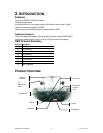
5. APPENDIX
DMX Primer
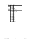
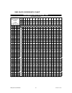
There are 512 channels in a DMX-512 connection. Channels may be assigned in any
manner. A fixture capable of receiving DMX 512 will require one or a number of sequential
channels. The user must assign a starting address on the fixture that indicates the first
channel reserved in the controller. There are many different types of DMX controllable
fixtures and they all may vary in the total number of channels required. Choosing a start
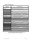
address should be planned in advance. Channels should never overlap. If they do, this will
result in erratic operation of the fixtures whose starting address is set incorrectly. You can
however, control multiple fixtures of the same type using the same starting address as
long as the intended result is that of unison movement or operation. In other words, the
fixtures will be slaved together and all respond exactly the same.
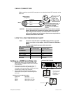
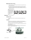
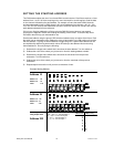
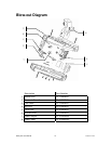
DMX fixtures are designed to receive data through a serial Daisy Chain. A Daisy Chain
connection is where the DATA OUT of one fixture connects to the DATA IN of the next
fixture. The order in which the fixtures are connected is not important and has no effect on
how a controller communicates to each fixture. Use an order that provides for the easiest
and most direct cabling. Connect fixtures using shielded two conductor twisted pair cable
with three pin XLR male to female connectors. The shield connection is pin 1, while pin 2
is Data Negative (S-) and pin 3 is Data positive (S+). CHAUVET carries 3-pin XLR DMX
compliant cables, DMX-10 (33’), DMX-4.5 (15’) and DMX-1.5 (5’)
Derby X™ User Manual 16 7/14/2008 1:27 PM