


Page 8 of 17 Intimidator Scan LED 300 User Manual (Rev. 3)
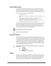
Mounting
Orientation
The Intimidator™ Scan LED 300 may be mounted in any position provided there is adequate
room for ventilation.
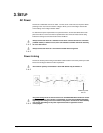
Rigging
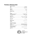
Be sure that the structure can support the weight of the fixture. Please see the “Technical
Specifications” section of this manual for a detailed weight listing. Mount the fixture securely. This
may be done with a screw, nut and bolt, or a hanging clamp. The hole in each bracket is 13 mm
in size. When rigging, consider routine maintenance and control panel access. Please see the
following notes on installation.
• If the power link out is intended to be used with multiple fixture, take into account the
length of each power cable, and mount the fixtures close enough to one another to
accommodate for this.
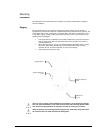
• When aiming the fixtures, you may use the bracket/yoke adjustment knob(s). Loosen
the knob(s), adjust to the desired angle, and then tighten the knob(s) by turning
clockwise. Do not use tools for this step, as it may cause damage.
• Safety cables must always be used.
There are two (2) rigging options available for this product. If using the hanging bracket,
then you must use a clamp or a nut & bolt to secure the product. If using the four rubber
feet, then the hanging bracket is not necessary and may be removed is you desire.
When the product is in the sitting position (using the four rubber feet), the product must
be secured so that it is stable and safe from falling down.
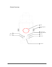
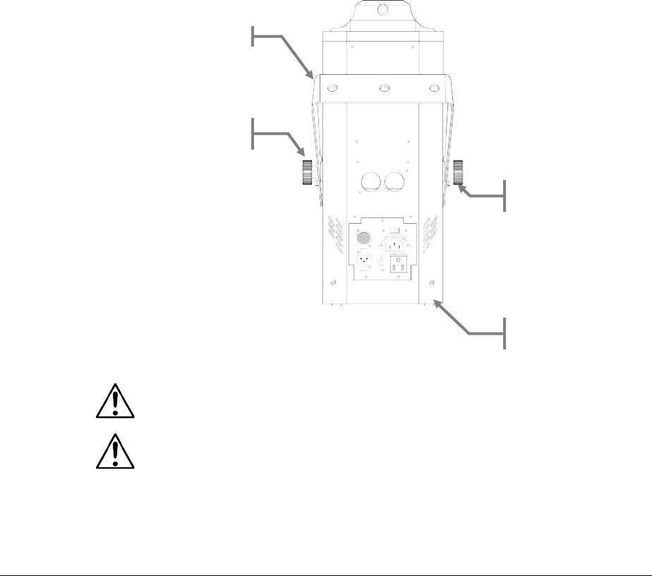
Hanging Bracket
Bracket Adjustment
Knob
Rubber Feet
(1 of 4)
Bracket Adjustment
Knob