


Page 10 For technical questions, please call 1-800-444-3353. Item 69275
SAFETY OPERATION MAINTENANCESETUP
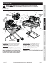
ASSEMBLY
TO PREVENT SERIOUS INJURY FROM ACCIDENTAL OPERATION:
Turn the Power Switch of the tool to its “OFF” position, remove the key, and unplug the tool
from its electrical outlet before assembling or making any adjustments to the tool.
Note: For additional information regarding the parts listed in the following pages,
refer to the Assembly Diagram near the end of this manual.
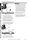
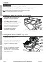
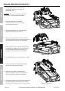
Installing the Water Tray Frame to the Leg Stand
1. Lock the Toggle Table Stop by pulling up on it
and turning it until the slot in the center of
the Stop is horizontal (left to right).
2. Pull the Table to the front of the Frame.
From under the right side of the Table, align the
hole in the rail with the pin in the Table Lock Lever.
Push the pin into the rail, locking the Table.
3. Align the holes on the Water Tray Frame with
the holes on the Stand (sold separately).
4. Insert Short Bolts through Washers
and into holes. Tighten securely.
Figure D: Water Tray Frame Installation
Stand
Water Tray
Frame
Washer
Short
Bolt
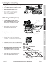
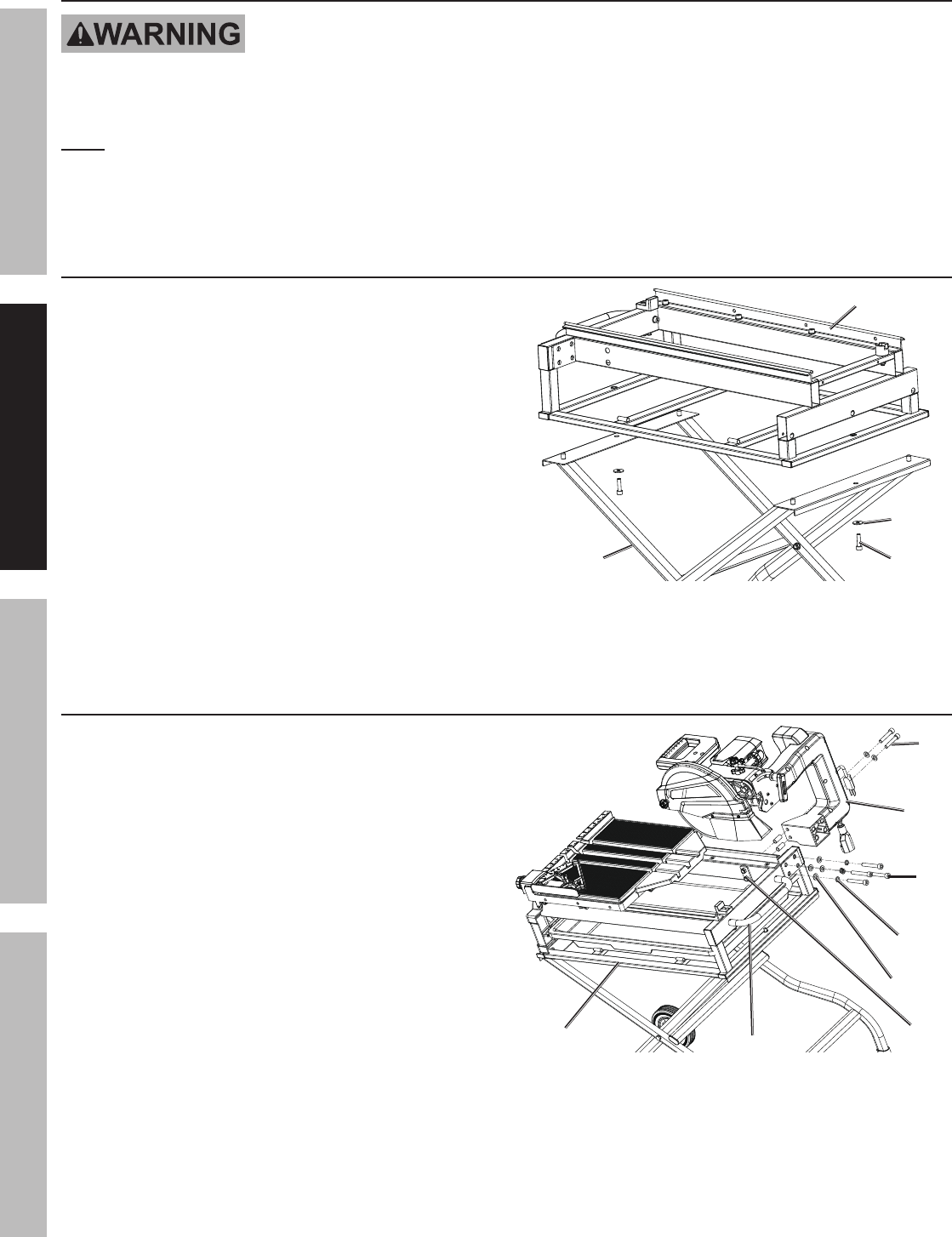
Installing Motor Head and Water Tray Frame
1. Install Handle to end of Water Tray Frame
using Bolts (119) and Washers.
2. Align the holes in the Motor Head assembly with
the holes on the side of the Water Tray Frame.
3. Insert two Short Bolts through Washers,
and then into holes on side of Motor Head.
Loosely secure using Lock Nuts.
4. Insert four Long Bolts through Lock Washers
and Washers. Insert into holes on end of
Water Tray Frame, as shown. Finger tighten.
5. Tighten all Bolts securely.
Figure E: Motor Head Installation
Motor
Head
Short
Bolt
Long
Bolt
Lock
Washer
Lock
Nut
Water
Tray Frame
Washer
Handle