


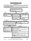
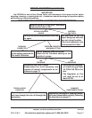
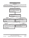
For technical questions, please call 1-800-444-3353;
Troubleshooting section at end of manual.
SKU 91814 PAGE 15
INSPECTION, MAINTENANCE, AND CLEANING
WARNING! Make sure the Power Switch of the Plasma Cutter is in its “OFF” position
and that the tool is unplugged from the electrical outlet before performing any inspec-
tion, maintenance, or cleaning procedures.
1. Before each use, inspect the general condition of the Plasma Cutter. Check for loose
cable connections, misalignment or binding of the fan, cracked or broken parts, damaged
electrical wiring, and any other condition that may affect its safe operation. If abnormal
noise or vibration occurs, have the problem corrected before further use. Do not use
damaged equipment.
2. Periodically: (1) recheck all nuts, bolts, and screws for tightness, (2) blow the dust from
the cooling vents with compressed air, & (3) clean the torch as explained below.
4. Verify that the cooling fan is operational before cutting.
5. If an odd smell comes from the unit during operation, stop all use. Have the Plasma
Cutter inspected and repaired by a qualified service technician.
6. Store the welder and accessories in a clean and dry location.
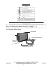
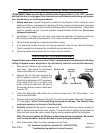
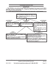
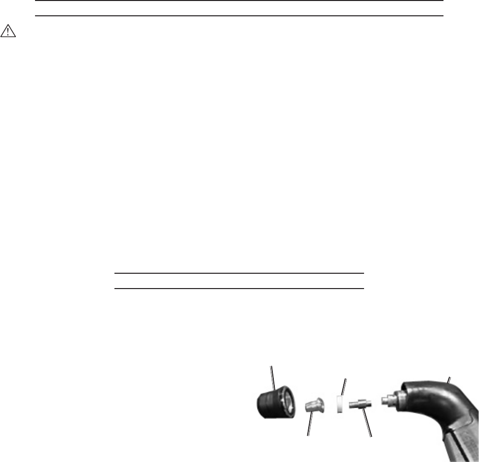
TORCH INSPECTION AND ASSEMBLY
Inspect before use and after every hour of use. Inadequate torch maintenance, including
failing to replace a worn electrode or tip, will destroy the torch and void the warranty.
1. Remove the Retainer and clean with
steel wool. Then check for cracks and
replace the Retainer if necessary.
2. Remove the Tip (55) and compare the
old Tip against a new Tip. Replace Tip
if the hole is deformed or 50% oversized.
If the inside of the Tip is not clean and
bright, clean with steel wool. Be sure to
remove any leftover pieces of steel wool
from the Tip.
3. Check the Electrode’s (56) center for a pit that is more than 1/16” (2mm) deep. If so,
replace the Electrode.
4. Remove and check the Ceramic Ring (57) for cracks and plugged side holes. Replace it
if it is damaged. Note: The Ceramic Ring only goes on one way. The Ceramic Ring
must seat squarely on the end of the Electrode.
5. Carefully reassemble the parts in reverse order. Thread retainer on only far enough to
hide its metal band inside the torch handle. The tip should be slightly spring loaded at
this point and should be able to move slightly when pressed against the workpiece.
Note: Do not overtighten the Retainer or Electrode during reassembly. Be careful
not to cross-thread or strip the threads of parts during reassembly.
6. After reassembly, check for proper operation of the Torch.
REV 07/05
Retainer (59)
Tip (55)
Ceramic
Ring (57)
Electrode (56)
Torch and
Cable (53)