


15
Warning
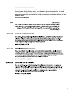
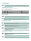
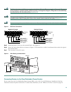
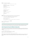
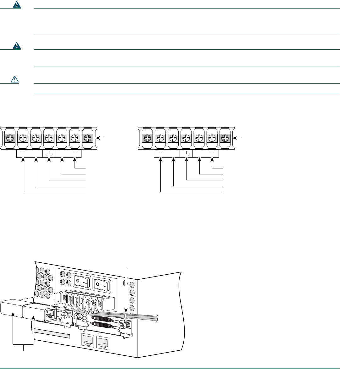
The illustration shows the DC power supply terminal block. Wire the DC power supply as illustrated. The proper
wiring sequence is ground to ground, positive to positive, and negative to negative. The ground wire should always
be connected first and disconnected last.
Statement 239
Warning
An exposed wire lead from a DC-input power source can conduct harmful levels of electricity. Be sure that no
exposed portion of the DC-input power source wire extends from the terminal block plug.
Statement 122
Caution Do not overtorque the terminal block contact screws. Recommended torque is 8.0 ± 0.5 in-lb (0.9 ± 0.05 N-m).
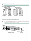
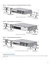
Figure 8 DC Power Connections
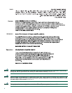
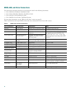
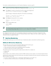
Step 5 Install the plastic covers over the terminal block. (See Figure 9.)
Step 6 Secure the wires using cable ties as shown in Figure 9. The chassis has a cable-tie attachment below and to the right of
the terminal block.
Step 7 Turn on power to the DC circuit.
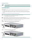
Figure 9 Wire Routing and Attachment
Connecting Routers to the Cisco Redundant Power System
If your router uses the Cisco Redundant Power System (RPS), refer to the Cisco RPS Hardware Installation Guide for
instructions about the power connections. To locate these documents, see the “Where to Go Next” section on page 23.
95965
Terminal
block
Negative DC output Positive DC input
A
+
B
+
Terminal
block
A
+
B
+
-DC, input B
Return, input B
Safety ground
Return, input A
-DC, input A
Return, input B
+DC, input B
Safety ground
+DC, input A
Return, input A
95824
AL
CD
LP
RD
TD
SEE MANUAL BEFORE INSTALLATION
DSU
56K
SEE MANU
AL BEFORE INST
ALLATION
Plastic covers
Cable tie
From DC
power
source