1-4
Cisco 819 Integrated Services Router Hardware Installation Guide
OL-23125-02
Chapter 1 Product Overview
General Description
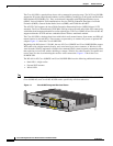
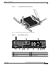
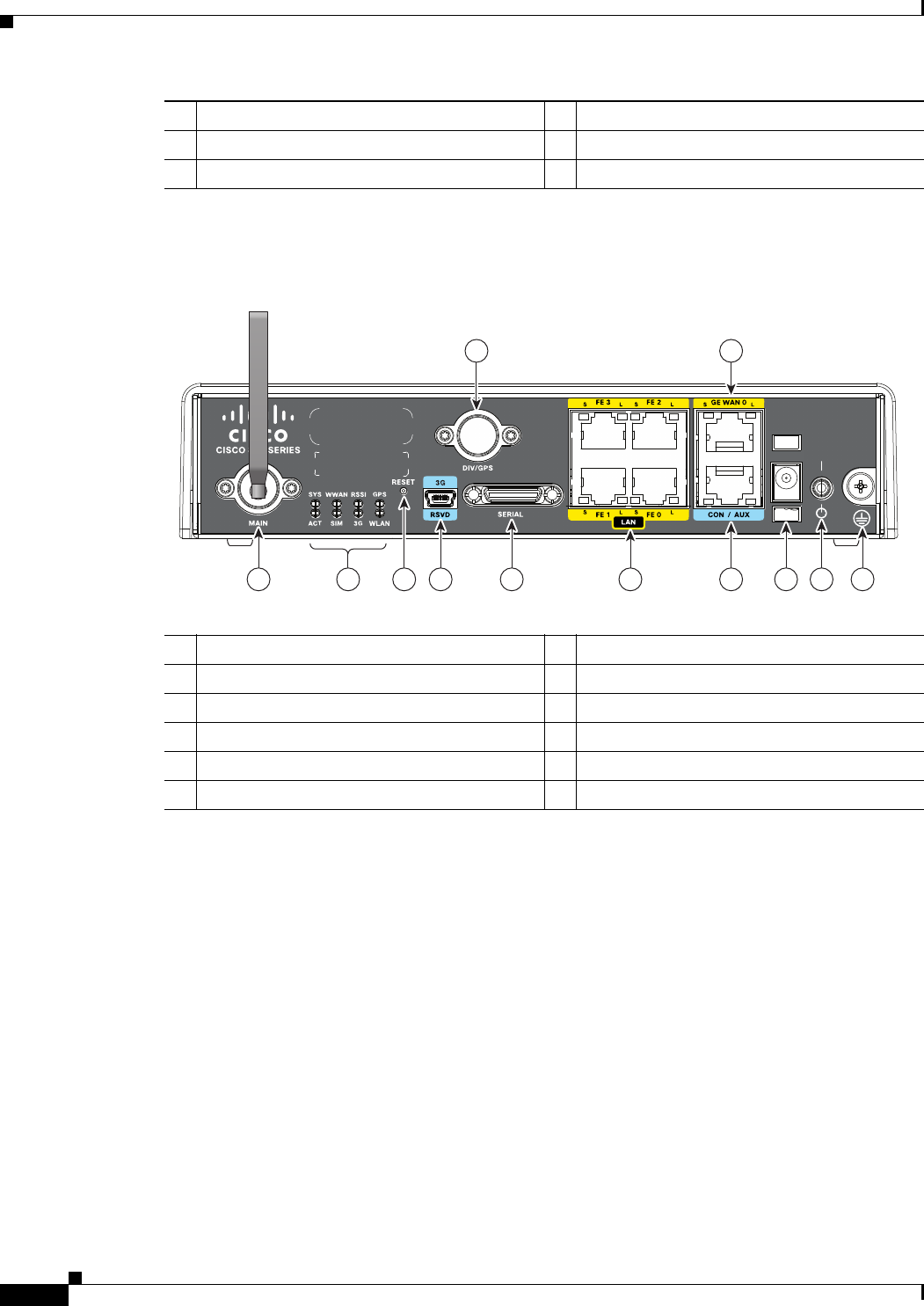
Figure 1-4 shows the front panel details of the Cisco 819HGW ISR.
Figure 1-4 Cisco 819HGW ISR Front Panel
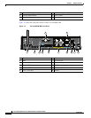
4 3G mini-USB diagnostic port 10 5 VDC molex power input
5 Diversity/GPS antenna 11 Power switch
6 12-in-1 serial port 12 Ground
344077
21 43 6 7 9 10 11 12
5 8
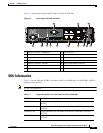
1 3G main antenna 7 FE ports
2 LEDs 8 GE WAN port
3 Reset button 9 Console/Aux port
4 3G mini-USB diagnostic port 10 5 VDC barrel-type power input
5 Diversity/GPS antenna 11 Power switch
6 12-in-1 serial port 12 Ground


