2-15
Cisco 819 Integrated Services Router Hardware Installation Guide
OL-23125-02
Chapter 2 Installing the Router
Installing the Router
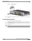
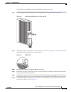
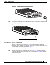
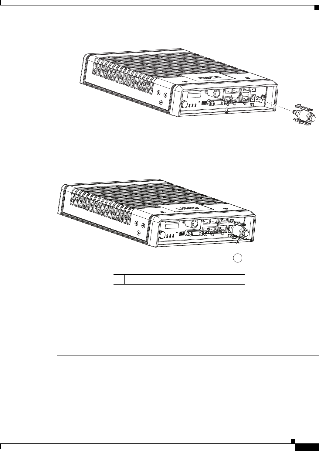
Figure 2-12 Installing Power Cord Lock onto the Router
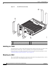
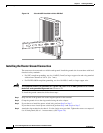
Step 4 To remove the power cord lock, use your thumb and index fingers to squeeze ends of tabs while pulling
away from the router. (See
Figure 2-13.)
Figure 2-13 End of Tabs
Installing the Power Switch Lock
The Cisco 819 ISRs have a power switch lock as an accessory. The power switch lock prevents
unauthorized access to a tampered proof router (for example, router in a bus). For the complete list of
Cisco 819 ISRs that support power switch lock, see
Table 1-4.
This section describes how to install the power switch lock.
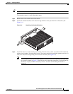
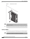
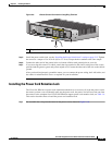
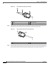
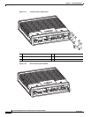
Step 1 Install the power switch lock by following the parts listed in Figure 2-14. All these parts are in the
accessory kit in their own bag. The ring terminal does not have to be installed. Figure 2-15 shows the
power switch lock installed.
285517
285518
1
1 End of tabs


