


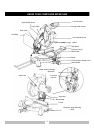
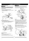
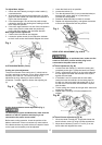
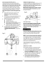

To Adjust Miter Angles:
1. Unlock the miter table by turning the miter handle (1)
counterclockwise.
2. While holding the positive-stop locking lever (2) down,
grasp the miter handle and rotate the miter table left or
right to the desired angle.
3. If the desired angle is one of the nine positive stops,
release the positive-stop locking lever making sure the
lever snaps into position.
4. If the miter angle desired is not one of the nine positive
stops, simply lock the miter table into position by
turning the miter handle in the clockwise direction.
Miter Angle Pointer Adjustment:
1. Position the miter table at zero degrees.
2. Loosen the pointer screw (4) and adjust the indicator
to the 0
°
mark on the miter scale & retighten the screw.
Fig. J
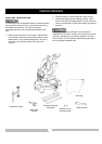
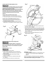
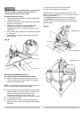
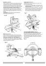
CUTTING ARM TRAVEL (FIG. K)
Cutting arm pivot adjustment
The pivot movement of the cutting arm (1) should not be
too tight; restricting movement, nor too loose; affecting the
accuracy of the saw cut. The correct locking nut (2)
adjustment is snug, allowing no side-to-side arm
movement. To adjust, tighten or loosen the adjusting nut
(2).
Cutting head downward travel adjustment (Fig. L)
To avoid injury from an accidental start, make sure the
switch is in the OFF position and the plug is not
connected to the power source outlet.
Before each cutting operation, check the position of the
blade to make sure it does not contact any metal surface.
If the blade contacts any metal surface, the depth of travel
on the upper arm assembly must be adjusted.
1. Lower the blade as far as possible.
2. Loosen the locknut (3).
3. Turn the adjustment bolt (4) out (counterclockwise) to
decrease the cutting depth or in (clockwise) to
increase the cutting depth.
4. Rotate the blade manually to check for contact.
5. Repeat until adjusted properly, and tighten the locknut
to secure the adjustment bolt into position.
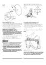
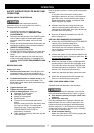
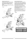
BEVEL STOP ADJUSTMENT (Fig. M & N)
To avoid injury from an accidental start, make sure the
switch is in the OFF position and the plug is not
connected to the power source outlet.
90
o
Bevel adjustment (Fig. M)
1. Loosen bevel lock handle (1) and tilt the cutting arm
completely to the right. Tighten the bevel lock handle.
2. Place a combination square (2) on the miter table with
the rule against the table and the heel of the square
against the saw blade.
3. If the blade is not 90
°
square with the miter table,
loosen the bevel lock handle, tilt the cutting head to
the left, turn the bevel angle adjustment bolt (3) in or
out with a 5mm hex wrench until the blade is square
with the table.
4. Tilt the cutting arm to back to the right at 90
°
bevel and
recheck for alignment.
5. Repeat steps 1 through 4 if further adjustment is
needed.
90
o
Bevel Pointer Adjustment (Fig. N)
1. When the blade is exactly 90
o
to the table loosen the
bevel indicator screw (5) using a Phillips screwdriver.
2.
Adjust bevel indicator (6) to the “0” mark (7) on the
bevel scale and retighten the screw.
Fig. L
Fig. M
Fig. K
13