


1
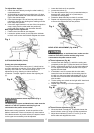
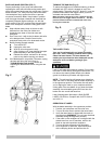
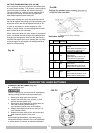
CUTTING CROWN MOLDING (FIG. AA, BB)
Your compound miter saw is suited for the difficult task
of cutting crown molding. To fit properly, crown molding
must be compound-mitered with extreme accuracy.
The two surfaces on a piece of crown molding that fit
flat against the ceiling and wall are at angles that,
when added together equal exactly 90°.
Most crown molding has a top rear angle (the section
that fits flat against the ceiling) of 52°and a bottom rear
angle (the section that fits flat against the wall) of 38°.
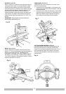
In order to accurately cut crown molding for a 90°
inside or outside corner, lay the molding with its broad
back surface flat on the saw table.
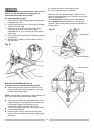
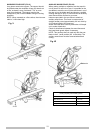
When setting the bevel and miter angles for compound
miters, remember that the settings are interdependent;
changing one changes the other, as well. Also keep in
mind that the angles from crown molding are very easy
for these angles to shift slightly, all settings should be
tested on scrap molding.
Fig. AA
Fig. BB
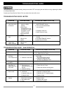
Bevel/Miter Settings
KEY BEVEL
SETTING
MITER
SETTING
TYPE OF CUT
Inside corner-Left side
IL 33.9° 31.6°
Right
1. Position top of molding against
fence.
2. Miter table set at RIGHT 31.6°.
3. LEFT side is finished piece.
Inside corner-Right side
IR 33.9° 31.6°
Left
1.Position bottom of molding
against fence.
2.Miter table set at LEFT 31.6°.
3.LEFT side is finished piece.
Outside corner-Left side
OL 33.9° 31.6°
Left
1.Position bottom of molding
against fence.
2.Miter table set at LEFT 31.6°.
3.RIGHT side is finished piece.
Outside corner-Right side
OR 33.9° 31.6°
Right
1.Position top of molding against
fence.
2.Miter table set at RIGHT 31.6°.
3.RIGHT side is finished piece.
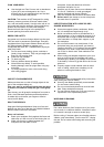
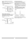
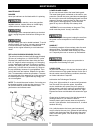
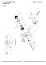
CHANGING THE BATTERIES (Fig. CC)
Unplug your saw.
Failure to unplug your saw could result in accidental
starting causing possible serious personal injury.
1. Remove the laser guide from the saw.
2. Loosen and remove the two screws (1), then
remove the laser guide cover.
3. Remove the three batteries by sliding them out
from their mounting braces using a
non-conductive devise such as a toothpick.
4. Replace the batteries that have a rating of 1.5
volts (Number LR44).
5. Replace the laser guide cover, two screws and
laser assembly onto the miter saw.
Note:
When replacing the batteries, the battery cover
should be thoroughly cleaned. Use a soft paintbrush
or similar device, to remove all sawdust and debris.
CHANGING THE LASER BATTERIES
FIG. CC
21