


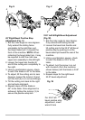

24 25
24 25
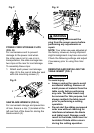
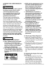
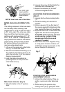
Bevel Scale Indicators (Fig. T)
1. When the blade is exactly 90°(0°) to
the table, loosen the bevel indicator
screws (1) using a #2 Phillips
screwdriver.
2. Adjust bevel indicators (2) to the
“0” mark on the bevel scale and
retighten the screws.
Fig. T
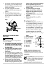
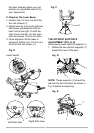
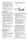
45° Left Bevel Positive Stop
Adjustment (Fig. U)
1. Set the miter angle to zero degrees.
Fully extend the sliding fence
completely to the left then pull the
bevel detent pin (1) toward the
front of the machine. NOTE: When
retracting the bevel detent pin, it may
be required to shift the miter saw
upper arm assembly to the left/right.
2. Loosen the bevel lock handle (2)
and tilt the cutting arm completely to
the left.
3. Using a combination square, check
to see if the blade is 45° to the table.
4. To adjust, tilt the cutting arm to zero
degrees, loosen the locknut (3) and
turn the bolt (4) in or out accordingly.
5. Tilt the cutting arm back to the left
and recheck alignment.
6. Repeat steps until the blade is
45° to the table. Once alignment is
achieved, tighten the locknut (3) to
secure the positive stop bolt.
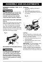
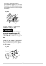
BEVEL STOP ADJUSTMENTS
(FIG. S, T, U, V)
To avoid injury from unexpected
starting or electrical shock, make
sure the trigger is released and
remove the power cord from the
power source.
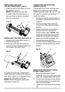
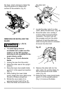
90°(0°) Bevel adjustment (Fig. S, T)
1. Loosen bevel lock handle (2) and tilt
the cutting arm while pushing in the
bevel detent pin (3-Fig. T) in against
the 0° bevel stop. Tighten the bevel
lock handle.
2. Place a combination square on the
miter table with the rule against the
table and heel of the square against
the saw blade.
3. If the blade is not 0° to the miter
table, loosen the four adjustment
bolts (1) at the rear of the unit with
a 5 mm hex wrench. Unlock the
bevel lock handle (2) and adjust
the cutting arm zero degrees to the
table. Tighten the bevel lock handle
and the four adjustment bolts after
alignment is achieved.
Fig. S
WARNING
!
1
2
3
2
1