


25
Fig. P
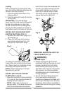
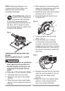
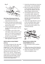
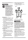
33.9° Bevel Adjustment (Fig. P)
1. Push the bevel detent pin (10) in
toward the front of the unit.
2. Unlock the bevel lock handle and tilt
the cutting arm to the crown molding
positive stop at 33.9
o
.
3. Using a combination square, check
to see if the blade angle is 33.9
o
to
the table.
4. If the blade is not at 33.9
o
to the
miter table, loosen locknut (11) and
use a 10 mm wrench to adjust the
bolt (12) in or out until the blade is
at 33.9
o
to the miter table.
5. Secure the locknut (11) into position
after alignment is achieved.
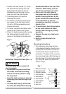
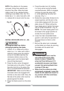
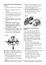
MITER ANGLE ADJUSTMENT
(FIG. Q)
The sliding compound miter saw scale
can be easily read, showing miter
angles from 0° to 45° to the left, and 0°
to 45° to the right. The miter saw table
has nine of the most common angle
setttings with positive stops at 0°, 15°,
22.5°, 31.6°, and 45°. These positive
stops position the blade at the desired
angle quickly and accurately. Follow
the process below for quickest and
most accurate adjustments.
10
7
9
8
11
12
1. Unlock the miter table by turning the
miter handle (1) counterclockwise.
2. Move the turntable while lifting up
on the positive stop locking lever
(2) to align the indicator (3) to the
desired degree measurement.
3. If the desired angle is one of the
nine positive stops, release the
positive stop locking lever, making
sure the lever snaps into position,
and then secure by tightening the
miter handle.
4. If the miter angle desired is not one
of the nine positive stops, simply
lock the miter table into position
by turning the miter handle in the
clockwise direction.
Fig. Q
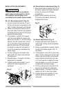
MITER SCALE INDICATOR
ADJUSTMENT (FIG. Q)
1. Move the table to the 0° positive
stop.
2. Loosen the screw (4) that holds the
indicator with a Phillips screwdriver.
3. Adjust the indicator (3) to the 0°
mark and retighten screw.
4
3
1
2