


38
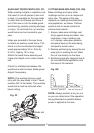
CUTTING CROWN MOLDING
(FIG. HH, II)
Your compound miter saw is suited
for the diffi cult task of cutting crown
molding. To fi t properly, crown molding
must be compound-mitered with
extreme accuracy. The two surfaces
on a piece of crown molding that fi t
fl at against the ceiling and wall are at
angles that, when added together,
equal exactly 90°.
Most crown molding has a top rear
angle (the section that fi ts fl at against
the ceiling) of 52°and a bottom rear
angle (the section that fi ts fl at against
the wall) of 38°.
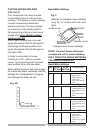
In order to accurately cut crown
molding for a 90° inside or outside
corner, lay the molding with its broad
back surface fl at on the saw table.
When setting the bevel and miter angles
for compound miters, remember that the
settings are interdependent; changing
one changes the other, as well.
Fig. HH
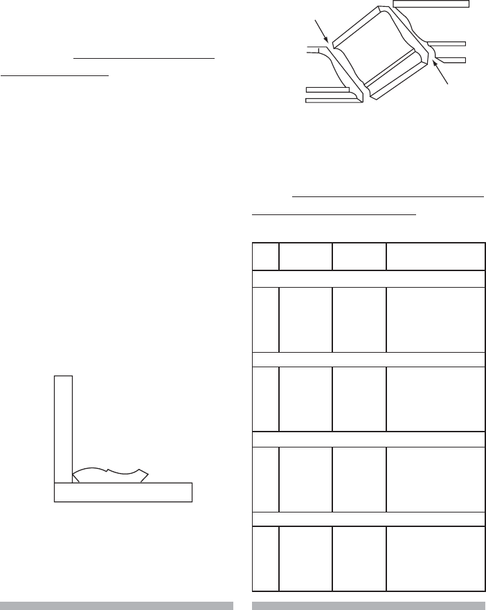
Bevel/Miter Settings
Fig. II
Settings for standard crown molding
lying flat on compound miter saw
table
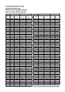
NOTE: The chart below references
a compound cut for crown molding
ONLY WHEN THE ANGLE BETWEEN
THE WALLS EQUALS 90°.
F
e
n
c
e
Miter saw table
Inside corner
Outside corner
Compound cut crown moldings
OR
OL
IR
IL
Bevel/Miter Settings
KEY BEVEL
SETTING
MITER
SETTING
TYPE OF CUT
Inside corner-Left side
IL
33.9° 31.6° Right 1. Position top of molding
against fence.
2. Miter table set at
RIGHT 31.6°.
3. LEFT side is fi nished
piece.
Inside corner-Right side
IR
33.9° 31.6° Left 1. Position bottom of
molding against fence.
2. Miter table set at LEFT
31.6°.
3. LEFT side is fi nished
piece.
Outside corner-Left side
OL
33.9° 31.6° Left 1. Position bottom of
molding against fence.
2. Miter table set at LEFT
31.6°.
3. RIGHT side is fi nished
piece.
Outside corner-Right side
OR
33.9° 31.6° Left 1. Position top of molding
against fence.
2. Miter table set at
RIGHT 31.6°.
3. RIGHT side is fi nished
piece.