


LUBRICAT|NGINSTRUCTIONS
(See Figure C)
rhe hlades of your Twin Cutter saw are
equipped with _dry cut teeth that under
normal cutting conditions do not need to
be lubricated. I towever, in extreme cutting
conditions, such as when you are sawing
into aluminum, copper, stainless steel and
cast iron, the wax lubricating device should
be used
1. Insert wax lubricating stick into wax
lubricating device.
2. Tern feeder wheel to apply lubricant to
blade, A 1/4 tun1 should provide adequate lubrication.
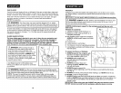
CUTTING INSTRUCTIONS cont.
Cutting Shaped Platea
up to t/8-in, thick (See Fig. tO)
1. When cntling shaped metal plate
ALWAYS support tile plate evenly on
bolh sides and in the middle with
support blocks. ]his will keep it from
flexing when cutting. This should be
done, whether you're using a clamping
table, or using adjustable clamps on a
flat wo*k table
l Fig. t0
8tick
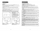
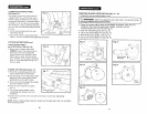
PLUNGE CUTTING (See Figure 11)
1. Raise the retractable guard into the
open position with your left hand.
2, Use the thumb of your left hand to hold
the guard in tile open position while
gripping ft_e saw's assist handle.
3. Turn on the saw and plunge the blades
into the matedal to be cut.
4. Push the saw forward to complete
the cut.
5. rum oft saw, allow blades to stop
completely, then remove saw from
workpiece.
6. Clean out the corners of the cut with a hand saw or sabre saw, depending
on project.
NOTE: When cutting roofing materials, blades must be kept clean with a tar and pitch
blade cleaning solvent
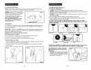
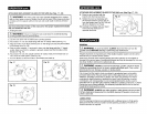
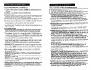
REMOVING BLADES FROM SAW (See Figs. 12 - 16)
1. Unplug the saw and allow blades to cool.
l z:_ WARNING: Failure to unplug the saw could result in accidental starting
causing possible serious personal injury,
2. Rotate the blades until the holes in both blades are aligned.Then place pie
attached to the wrench through holes in blades. Unscrew Lock Nut
counterclockwise and remove (see Fig. 12).
3. Open the retractable guard (see Fig. 13).
4. Lift up and remove Blade "B" (see Fig. 14).
5. Remove the arbor adapter (see Fig. 15).
6. Lift up and remove Blade "A" (see Fig. 16).
Fig. 13
Blade Guard
Retracted
Fig, 15
Adapter
Fig. 16
16 17