


10
11
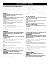
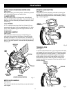
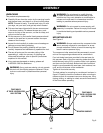
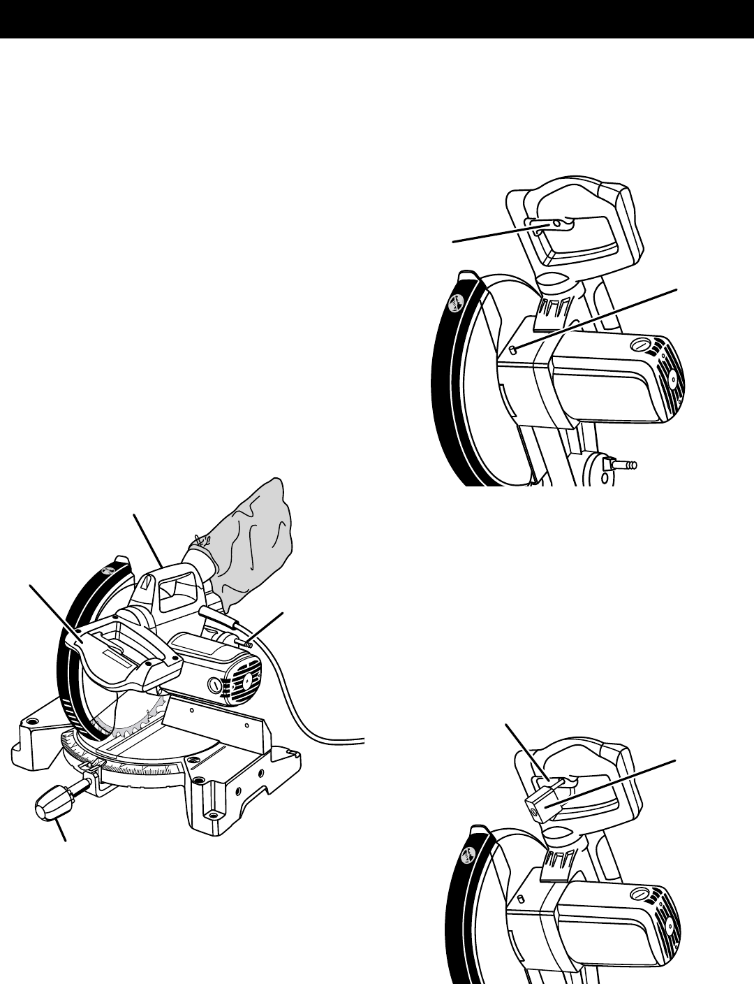
SPINDLE
LOCK BUTTON
SWITCH
TRIGGER
Fig. 3
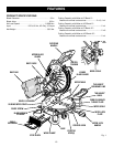
FEATURES
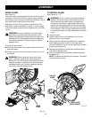
PADLOCK
SWITCH
TRIGGER
Fig. 4
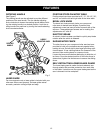
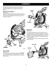
Fig. 2
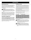
KNOW YOUR COMPOUND MITER SAW
See Figure 1.
Before attempting to use this product, familiarize yourself
with all operating features and safety rules.
15 AMP MOTOR
Your saw has a powerful 15 amp motor with sufficient
power to handle tough cutting jobs. It is made with all ball
bearings, and has externally accessible brushes for ease
of servicing.
10 in. BLADE
A 10 in. carbide-tipped saw blade is included with your
compound miter saw. It will cut materials up to 2 in. thick
or 6 in. wide, depending upon the angle at which the cut
is being made.
CARRYING HANDLE
See Figure 2.
For convenience when carrying or transporting your
miter saw from one place to another, a carrying handle
has been provided on top of the saw arm. To transport,
turn off and unplug your saw, then lower the saw arm and
lock it in the down position. Lock saw arm by depressing
the lock pin.
SPINDLE LOCK BUTTON
See Figure 3.
A spindle lock button has been provided for locking the
spindle which keeps the blade in your saw from rotating.
Depress and hold the lock button while installing, chang-
ing, or removing blade.
TRIGGER LOCK
See Figure 4.
To prevent unauthorized use of your compound miter saw,
we suggest that you disconnect it from the power supply
and lock the switch in the off position. To lock the switch,
install a padlock (not included) through the hole in the
switch trigger. A lock with a long shackle up to 9/32 in.
diameter may be used. When the lock is installed and
locked, the switch is inoperable. Store the padlock key in
another location.
SAW ARM
LOCKED IN DOWN POSITION
LOCK PIN
MITER LOCK HANDLE
See Figure 2.
The miter lock handle securely locks your saw at desired
miter angles.
CARRYING
HANDLE
SAW
ARM
MITER LOCK
HANDLE