


22
23
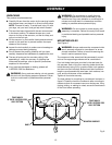
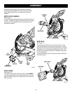
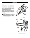
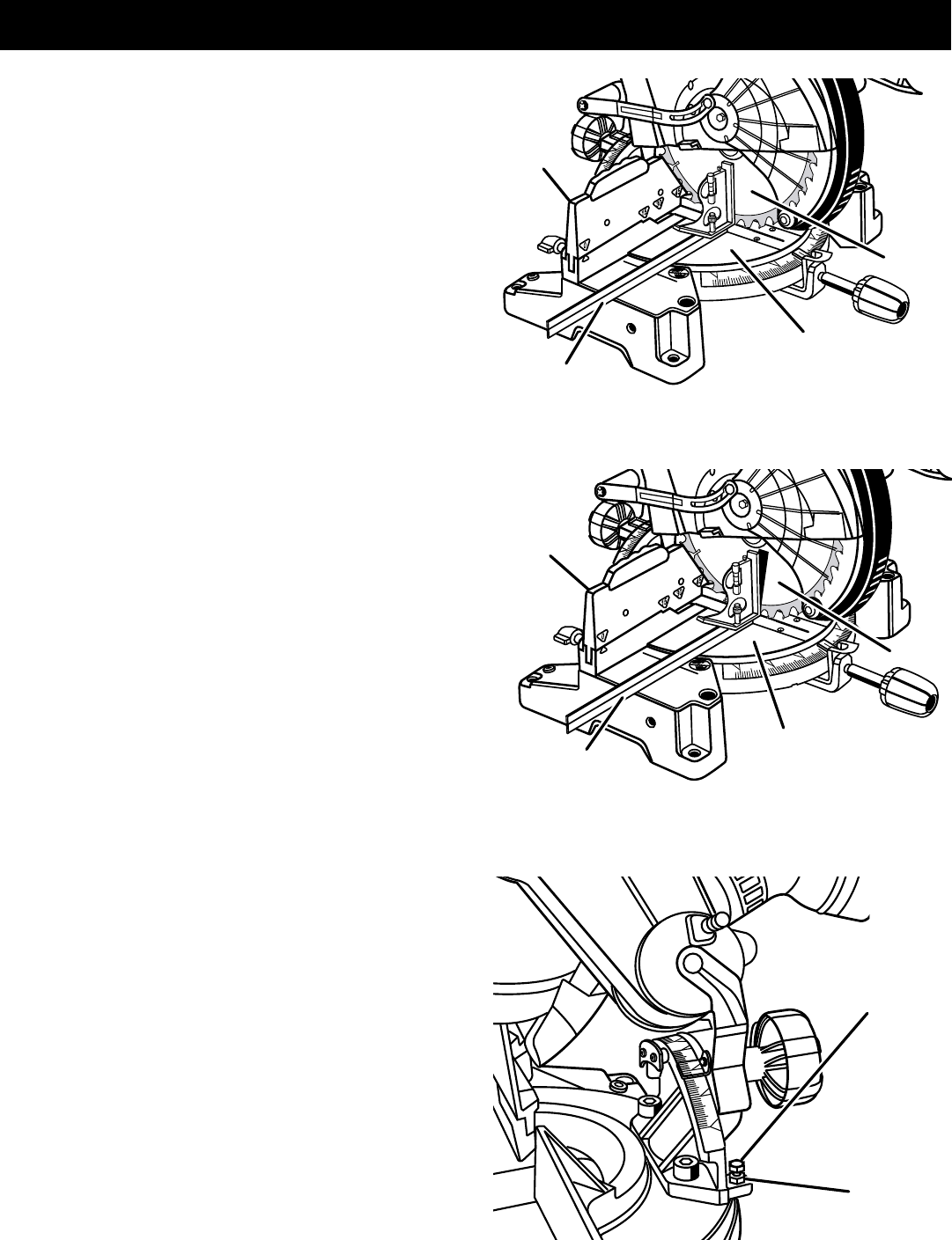
ASSEMBLY
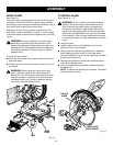
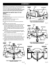
FENCE
MITER
TABLE
COMBINATION
SQUARE
BLADE
Fig. 28
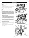
CORRECT VIEW OF BLADE
SQUARE WITH MITER TABLE
VIEW OF BLADE NOT SQUARE WITH MITER
TABLE, ADJUSTMENTS ARE REQUIRED
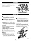
Fig. 29
SQUARING THE BLADE TO THE MITER
TABLE
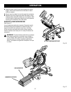
See Figures 28 - 30.
n Unplug the saw.
n Pull the saw arm all the way down and engage the lock
pin to hold the saw arm in transport position.
n Loosen the miter lock handles.
n Rotate the miter table until the pointer is positioned
at 0
°
.
n Securely tighten the miter lock handles.
n Loosen bevel lock knob and set saw arm at 0
°
bevel
(blade set 90
°
to miter table). Tighten bevel lock knob.
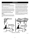
n Place a combination square against the miter table and
the flat part of saw blade.
NOTE: Make sure that the square contacts the flat part
of the saw blade, not the blade teeth.
n Rotate the blade by hand and check the blade-to-table
alignment at several points.
n The edge of the square and the blade should be paral-
lel.
n If the top or bottom of the blade angles away from the
square as shown in figure 29, adjustments are needed.
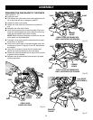
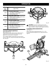
n Using a 10 mm wrench or adjustable wrench, loosen
the lock nut securing positive stop adjustment screw.
Also loosen bevel lock knob.
n Adjust positive stop adjustment screw to bring blade
into alignment with the square.
n Retighten bevel lock knob. Next, retighten lock nut
securing the positive stop adjustment screw. Recheck
blade-to-table alignment.
NOTE: The above procedure can be used to check
squareness of the blade to the miter table at both 0
°
and 45
°
angles.
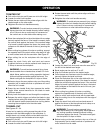
FENCE
MITER
TABLE
COMBINATION
SQUARE
BLADE
Fig. 30
LOCK
NUT(S)
POSITIVE STOP
ADJUSTMENT
SCREW FOR
45
°
ANGLES