


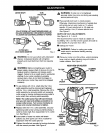
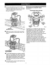
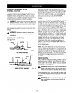

• Turnthedepthadjustingringuntiltipofcutter
touchesflatsurface(zerodepthofcut).See Figure
6. Next turn depth indicator ring until the zero lines
up with the indLcator point on front of motor
housing. See Figure 5.
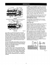
DEPTH OF CUT ADJUSTMENTS WHEN ROUTER
IS MOUNTED TO A ROUTER TABLE
See Figure 8.
FOR ROUTER TABLE USEONLY
CU'I-rERAT
ZERODEPTHOF CUT Fig. 6
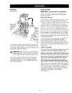
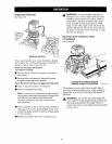
• Position your router so that the cutter can extend
below the subbase for desired depth setting, See
Figure 7.
BASE
DEPTH
INDICATOR
RING
INDICATOR
POINT Fig. 8
The depth of cut is readable from both sides of the
depth adjusting ring. There is a depth indicator ring
and indicator point on both sides of the depth
adjusting ring. The bottom ring is convenient when
using your router mounted to a router table. The
indicator point on the base should also be used when
using your router mounted to a router table.
The depth indicator rings are identical parts.
Therefore, when you have your router mounted
upside clown on a router table, you set depth of cut by
reading the scale differently. Set the cutter at zero
depth of cut, rotate depth indicator ring to desired
depth of cut on the scale, then turn depth adjusting
ring back to zero depth of cut and lock clamping lever
securely.
CUI"FEREXTENDED
BELOWSUBBASE Fig. 7
• Turn the depth adjusting ring to obtain the desired
depth of cut. The distance the cutter moves can be
read on the depth adjusting ring. Each mark on the
depth adjusting ring indicates 1/64 inch change in
depth setting. One indicator point is located on
front of the motor housing, the other one is located
on the base.
• Lock clamping lever, securing depth adjusting ring
to motor housing and base.
9