


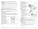


DIRECTION-OF-ROTATION SELECTOR (FORWARD/CENTER LOCK/
REVERSE) (Fig. 5)
The direction of bit rotation is reversible and is controlled by a selector located
above the trigger switch. With the Right-Angle Impact Driver held in normal
operating position:
1. Position the direction-of-rotation selector to the left of the tool for forward
rotation.
2. Position the direction-of-rotation selector to the right of the tool for reverse
rotation.
3. Setting the switch in the OFF (center lock) position helps reduce the
possibility of accidental starting when not in use.
_i, CAUTION: To prevent gear damage, always allow the 12V Right-Angle
Impact Driver to come to a complete stop before changing the direction of
rotation.
NOTE: The 12V Right-Angle Impact Driver will not run unless the direction of
rotation selector is engaged fully to the left or right.
ELECTRIC BRAKE
To stop the 12V Right-Angle Impact Driver, release the trigger switch and
allow the tool to come to a complete stop. The electric brake quickly stops the
rotation. This feature engages automatically when you release the trigger switch.
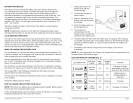
FuelGauge (Fig. 6)
This tool is equipped with a
FuelGauge that indicates the
battery pack charge level.
The green LED on the
FuelGauge indicates that the
battery is fully charged.
The orange LED on the
FuelGauge indicates that the
battery has used approximately
one half of its charge
The red LED on the FuelGauge
indicates the battery pack
is depleted and needs to be
charged.
Fig. 6
tP
J.z/
C
FuelGauge
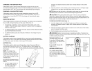
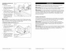
LED WORKLIGHT (Fig. 7)
The LED worklight, located on
the front of the 12V Right-Angle
Impact Driver, will illuminate
when the trigger switch is
depressed.
This provides additional light on
the surface of the workpiece for
operation in lower-light areas.
The LED worklight will turn
off when the trigger switch is
released.
INSTALLING BITS (Fig. 8)
1.
2.
3.
Lock the trigger switch by
placing the direction-of-
rotation selector in the OFF
(center) position.
With one hand, pull the
sleeve toward the front of
the tool, and hold it in place.
With the other hand, insert
a 1/4-in. shank bit into the
hexagonal hole in the bit
retainer.
Fig. 7
LED Worklight
Fig. 8
4. Release the sleeve and
check that it returns to its
original position.
_i, WARNING: If the sleeve does not return to its original position, the bit is not
correctly installed. Retry until the bit is properly installed.
WARNING: Use protective gloves when removing the bit from the tool, or
first allow the bit to cool down. The bit may be hot after prolonged use.
REMOVING BITS (Fig. 8)
1. Lock the trigger switch by placing the direction-of rotation selector in the
OFF (center) position.
2. Pull the sleeve towards the front of the tool, and hold it in place.
3. Remove the bit from the hexagonal hole in the bit retainer.
4. Release the sleeve.
17562 ManuaLRevised_$O 0607 Page 16 17562 ManuaLRevised_lO 0607 Page 17