


22
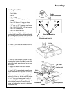
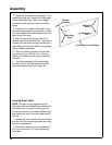
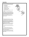
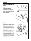
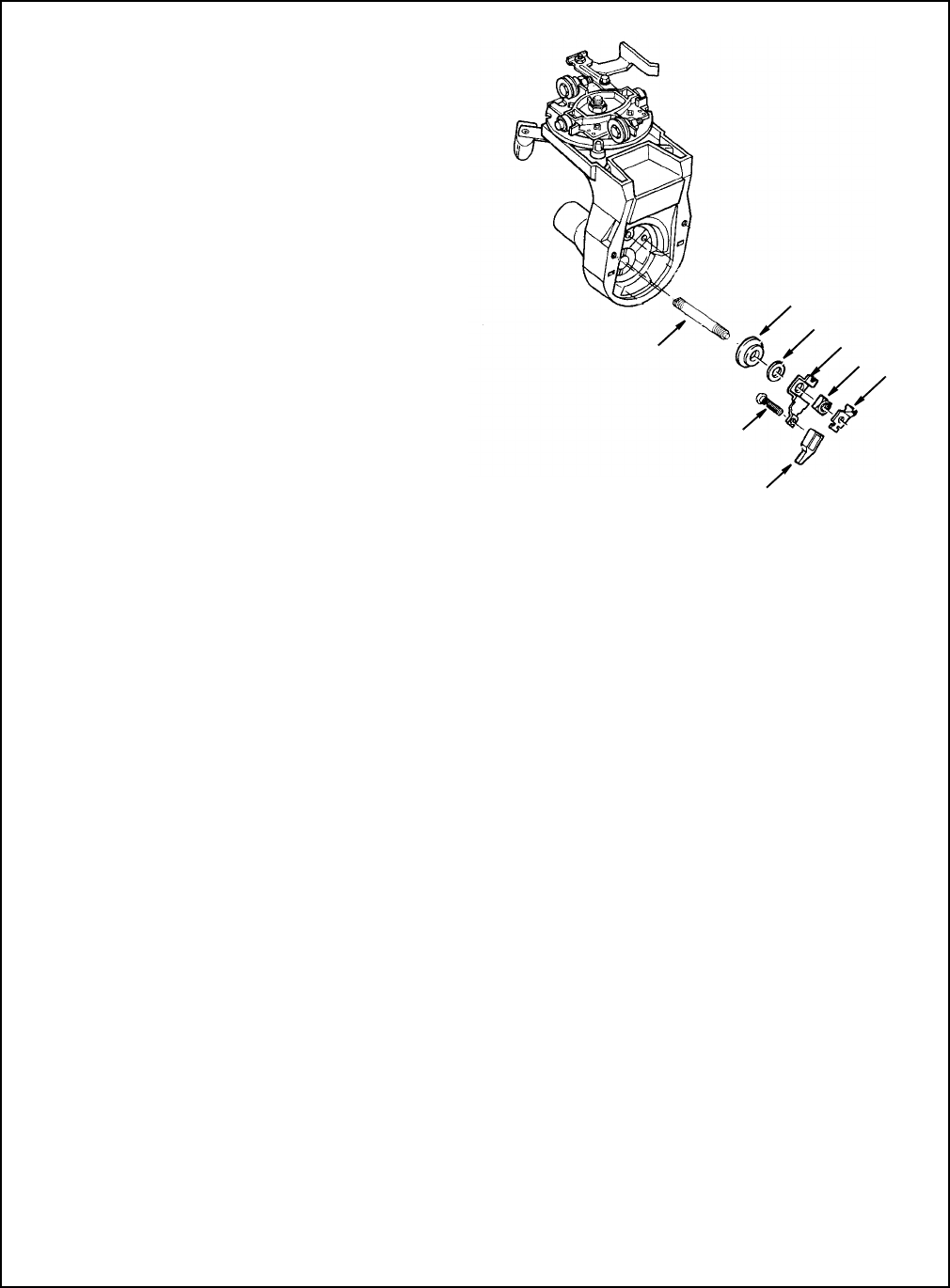
7. The following items can now be removed
from the front of the yoke as an assembly:
a. Shaft support
b. Shaft washer
c. Washer .505 x 7/8 x 1/16
d. Bevel lock lever
e. Square nut 1/2 x 13
f. Bevel spring wedge
g. Bevel lock knob
h. Screw, pan head plastite no. 8 x 3/8"
long
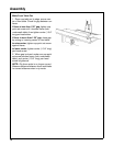
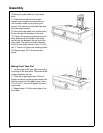
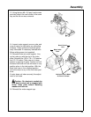
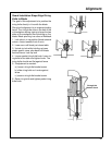
8. Remove the bevel spring wedge from
this assembly by rotating shaft support coun-
terclockwise until it comes out of the square
nut located between the bevel lock lever and
the bevel spring wedge. Do not remove any
other items. Remove square nut then
remove the bevel spring wedge from the
bevel lock lever.
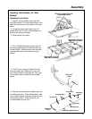
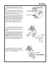
9. Replace the bevel lock lever, with new
one supplied with kit. Reinsert bevel wedge
in new bevel lock lever. Reinsert square nut
between bevel lock lever and bevel lock
wedge. Reinsert the shaft support and rotate
clockwise until end of shaft is flush with the
rear of the bevel lock wedge.
NOTE: Bevel lock lever must be replaced to
prevent interference with guard assembly.
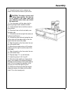
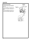
10. Reinstall the shaft support assembly into
the yoke.
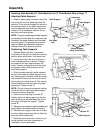
11. Reinstall the bevel spring using the
screw previously removed. Make sure the
slot in the bevel spring is in the groove of the
index pin before tightening.
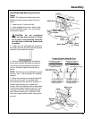
12. Reinstall the yoke cover using the plas-
tite screws previously removed or by clipping
back in place.
c
d
e
f
g
h
a
b
Assembly