G8693 Mini Shaper -11-
SECTION 4: ASSEMBLY
Spindle Shaft
For Your Own Safety, Never Connect To Power
Source Until All Assembly Steps Are Complete,
And You Have Read And Understand The Safety
And Operational Instructions.
Typically, the Spindle Shaft is already installed
from the factory. To remove the Spindle, reverse
the following steps.
1. Place the Shaper Nut (REF 36) onto the
Spindle Shaft (REF 35) and insert the Shaft
into the Spindle Bore. See Figure 2.
2. Shaper Nut must be screwed onto the thread-
ed portion of the Spindle Bore.
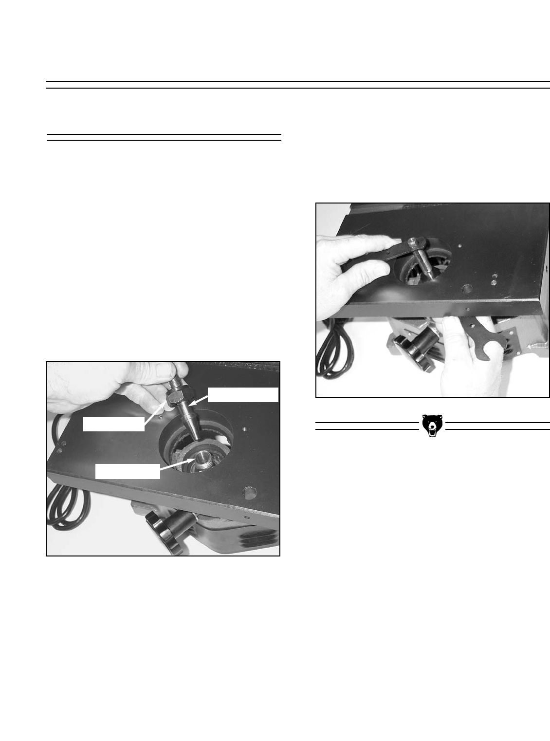
3. Lock the assembly in place by tightening the
Shaper Nut with the wrenches provided. See
Figure 3.
NOTE: If you would like to use Router bits
instead of Shaper cutters, see section on
“Using Router Bits” for instructions.
Figure 2. Set Spindle into hole.
Figure 3. Tightening Spindle.
Spindle Shaft
Shaper Nut
Spindle Bore