


iLux™ Expansion Module Crestron CLS-EXP-DIMFLV
Physical Description
This section provides information on the connections and
indicators available on the CLS-EXP-DIMFLV.
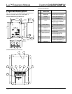
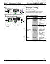
CLS-EXP-DIMFLV Overall Dimensions
8.82 in
(22.40 cm)
5.79 in
(14.71 cm)
4.99 in
(12.67 cm)
3.07 in
(7.80 cm)
3.18 in
(8.08 cm)
Ø 0.19 in
(Ø 0.48 cm)
8.31 in
(21.11 cm)
7.31 in
(18.57 cm)
0.50 in
(1.27 cm)
2.02 in
(5.21 cm)
1.56 in
(3.96 cm)
Ø 0.25 in
(Ø 0.64 cm)
6.39 in
(16.23 cm)
1.64 in
(4.17 cm)
1.64 in
(4.17 cm)
CLS-EXP-DIMFLV (cover removed)
3
10
4 5 6
1 2
7 8 9
Connectors & Indicators
# CONNECTORS &
INDICATORS
DESCRIPTION
1 LOAD STATE
INDICATOR
(1) Red LED behind front panel,
illuminates when load output is
on
2 POWER
INDICATOR
(1) Green LED behind front
panel, indicates power is
applied to the HOT terminal
3 CTRL (1) Captive screw terminal, for
control input from compatible
dimmer or switch
4 NEUT (INPUT) (1) Captive screw terminal, for
neutral connection for control
input
5 SW OUT (1) Captive screw terminal for
switched output to the load
6 HOT (1) Captive screw terminal, for
line power input
7 NEUT (OUTPUT) (1) Captive screw terminal,
neutral connection for line
power input and load
8 + (1) Captive screw terminal, “+”
connection to dimmable ballast
9 - (1) Captive screw terminal, “-”
connection to dimmable ballast
10 GROUND (1) Chassis ground bus bar
4 • iLux™ Expansion Module: CLS-EXP-DIMFLV Installation Guide – DOC. 6680A