


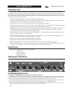
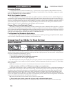

BYPASS Button and LED:
Depress this button to “hard-wire bypass” the 166XL’s circuitry,(i.e., unaltered input signal will pass through the unit
even if it is unplugged). Note that BYPASS works independently for each channel, even when the unit is stereo-coupled
(via the STEREO COUPLE button).
In Bypass mode, the input is sent directly to the output, bypassing the 166XL’s processing and controls and presenting
unaltered input signal at the 166XL’s OUTPUT. Bypass mode is especially useful for making comparisons between
processed and unprocessed signals.
The BYPASS LED turns On in Bypass mode if the 166XL is being provided with AC power.
LIMITER Section
PEAKSTOP LEVEL Control and LED:
This control allows you to set the maximum peak output level of the 166XL regardless of any other control. PeakStop
comes after the compression, gating and output gain circuitry; this provides for an absolute limit to be put on the peak
excursions at the output. PeakStop works instantaneously; you can apply moderate amounts of dbx’s OverEasy compres-
sion and still be protected from large transients, other short-term overloads and overmodulation.
PeakStop is a smooth well-controlled soft clipper whose behavior is sonically similar to the gentleness of OverEasy
compression; its clipping is much preferable to a power amp’s or analog-to-digital converter’s. PeakStop rounds the cor-
ners of a peak rather than cutting it off sharply. By making a signal’s leading and trailing edges curved instead of sharply
angled, it reduces the amount of higher odd-order, offensive-sounding harmonics that conventional hard clipping causes.
The level at which PEAKSTOP is activated is adjustable from +0dBu to +20dBu. Note that small signal excursions
above the set value of PEAKSTOP are possible, to allow the rounding to occur. Therefore, for applications where you
must not exceed a given ceiling, set the PEAKSTOP control 1dB to 2dB below the ceiling.
The PEAKSTOP LED illuminates whenever peaks attempt to exceed PeakStop level and are reduced in amplitude. If
the PeakStop LED illuminates when the PEAKSTOP LEVEL control is set to +20dBu, the headroom capabilities of the
166XL are being exceeded and hard clipping is occurring.
MASTER Section
STEREO COUPLE Button and LED:
This button toggles the unit between stereo and dual mono operation. Press the STEREO COUPLE button In for stereo
operation where Channel 1 becomes the master controller for both channels. All of Channel 2’s controls, buttons, and
LEDs will be disabled (except for Channel 2’s BYPASS, SIDECHAIN ENABLE, and CONTOUR buttons, and its GAIN
REDUCTION LEDs), since Channel 2 is the “slave.” Note that the detection circuitry senses the true RMS levels of the
combined signal, so it is unaffected by phase shifts (or other discrepancies) between the channels. This ensures stereo
compression without loss of imaging stability.
With the STEREO COUPLE button Out, the unit functions as two separate mono compressor/gates, each with its own
independent controls.
The STEREO COUPLE LED indicates that the 166XL is stereo-coupled.
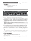
Rear Panel
INPUT (BALANCED) Jacks:
The Tip/Ring/Sleeve phone jack and XLR-type jack are wired in parallel; either INPUT will accept an audio signal for
processing by the 166XL. The phone jack accepts a standard TRS 1/4” phone plug for a balanced input source, or a 2-cir-
cuit (Tip/Sleeve) 1/4” phone plug for an unbalanced source. The XLR-type jack is wired pin 2 HOT (+), pin 3 COLD (-)
and pin 1 GROUND.
Note: Only one input jack should be used at a time, except for “splitter” applications where one input jack is used as an input
and the other input jack is used as an output (see “Using the SIDECHAIN INSERT” section on page 16). Since a given pair of
channel input jacks (e.g., Channel 1 XLR INPUT and Channel 1 1/4” INPUT) are internally connected (TIP = Pin 2, RING =
Pin 3, SLEEVE = Pin 1), if one of the jacks is unbalanced, then the other jack will be unbalanced. For example, if a 1/4”
INPUT jack is used with a mono cable, and is therefore unbalanced, the XLR INPUT jack will also be unbalanced (Pin 3 short-
ed to ground).
OPERATING LEVEL Switch:
This switch selects between a -10dBV and +4dBu nominal operating level. When the switch is in the in position, a
-10dBV operating level is selected. When it is in the out position +4dBu is selected. A -10dBV operating level should be
dbx 166XL COMPRESSOR / GATE
5