


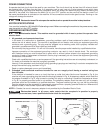

RISK OF UNSAFE OPERATION. You must secure the plywood base to the floor or supporting
surface if the drill press has any tendency to vibrate, slide, or walk during normal operation.
11
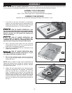
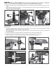
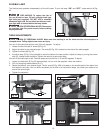
6. Attach the column (A) Fig. 6 to the base (B) using the four M10x40mm hex head screws (C), three of which are
shown.
7. Attach the table adjusting handle (D) Fig. 7 to the worm gear shaft (E). Tighten the screw (F) against the flat on the
shaft with the 3mm wrench supplied.
8. Thread the table clamp handle (G) Fig. 8 in the hole in rear of table bracket.
Fig. 6
Fig. 7
Fig. 8
A
C
B
C
D
E
F
G
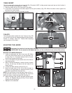
LIFTING HAZARD. The drill press table is heavy. Two people may be needed to attach it to the drill
press column.
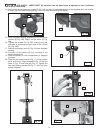
9. To attach the table to the knuckle, align the pilot face (H) Fig. 9 of the knuckle (K) with the table support (J) before
tightening the table bolt (D) Fig. 10A with the 14mm hex wrench.
10. Check the scale (F) Fig. 9. Ensure the hairline pointer (E) Fig. 10 on the knuckle lines up with zero (0) on the scale (F)
on the table support.
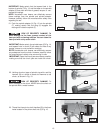
11. To attach the forward tilt locking lever (G) Fig. 10A, place the lever on the trunnion clamp nut (H).
12. Place the spring (I) on the slotted screw (J). Insert the screw into the lever and trunnion clamp nut.
13. Tighten the screw (J) until it bottoms. The lever should move up and down on the screw.
Fig. 9
Fig. 10
Fig. 11
Fig. 12
H
K
J
F
F
E
D
G
H
I
J