


14
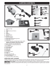
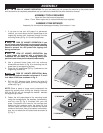
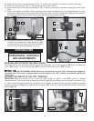
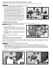
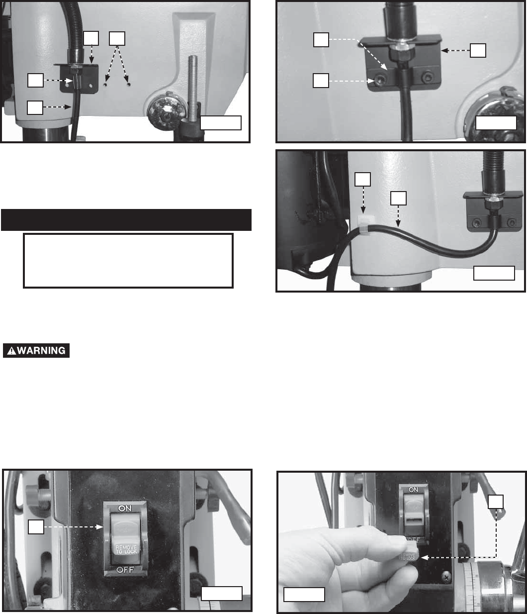
24. Align the two holes in the lamp bracket (A) Fig. 17, with the two holes (B) on the side of the drill press head.
25. Place the cord bushing (C) Fig. 17, around the top of the lamp cord (D)
26. Align the two holes in the lamp cord bracket (F) Fig. 18 with the two holes in the lamp bracket (A) and drill press
head.
27. Place a 1/4" washer onto a M6x1x12mm cap head screw. Insert the screw (G) Fig. 18 through the hole in the cord
strain relief bracket and the lamp bracket and thread the screw into the drill press head. Repeat this process for
the remaining hole in the cord strain relief bracket and tighten both screws securely.
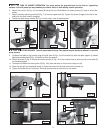
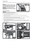
28. Peel backing from cord clamp (H) Fig. 19, and apply
clamp at the location shown. Make certain the lamp
cord is routed out of the way of the drill, then secure
cord (J) to cord clamp (H) as shown in Fig. 19.
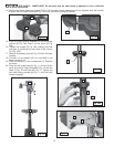
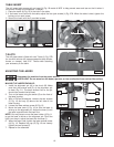
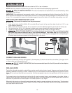
The switch (A) Fig. 20 is located on the front of the drill press head. To turn the drill press “ON” move the switch up
to the “ON” position. To turn the drill press “OFF” move the switch down to the “OFF” position.
RISK OF PERSONAL INJURY. Make sure that the switch is in the “OFF” position before plugging in
the power cord. In the event of a power failure, move the switch to the “OFF” position. an accidental start-up can
cause injury.
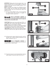
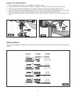
IMPORTANT: When the machine is not in use, the switch should be locked in the “OFF” position to prevent
unauthorized use. This can be done by grasping the switch toggle (B) and pulling it out of the switch, as shown in Fig.
21. With the switch toggle (B) removed, the switch will not operate. However, should the switch toggle be removed
while the drill press is operating, the switch can be turned “OFF” once, but cannot be restarted without inserting the
switch toggle (B).
OPERATIONAL CONTROLS
AND ADJUSTMENTS
OPERATIONS
A
B
C
D
F
A
G
H
J
STARTING AND STOPPING THE DRILL PRESS
A
LOCKING THE SWITCH IN THE “OFF” POSITION
B
Fig. 17 Fig. 18
Fig. 19
Fig. 20
Fig. 21