


16
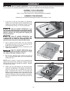
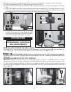
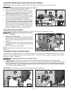
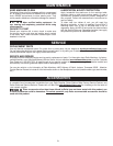
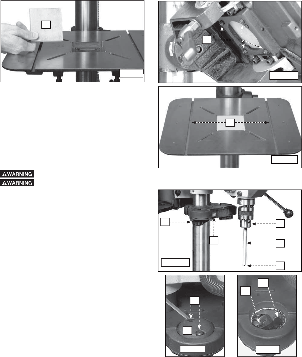
TABLE INSERT
The drill press table comes with an insert (H) Fig. 26 made of MDF to help prevent wear and tear on the bit when it
drills down through the workpiece. To adjust:
1. Place the insert (H) Fig. 26 in the hole in the table.
2. If the insert is not level with the table, adjust the four jack screws (J) Fig. 27A. When the table is level, tighten the
locking nut on each screw.
3. Secure the insert with the 2 provided screws.
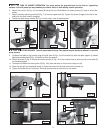
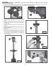
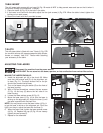
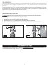
MAKING THE LASERS PARALLEL
1. Install the alignment pin (A) in the chuck (B). Make
sure that the pointed end (C) of the alignment pin
is down (Fig. L1). The black scribed line on the pin
should face toward the left laser.
2. Turn on the lasers using the switch (D) on the front of
the laser housing.
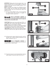
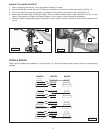
3. With a Phillips screwdriver, remove the two screws
(F) Fig. L2 and cap (G) above the left side of the
laser housing.
4. Loosen the laser retainer screw (H) Fig. L3.
5. Move the laser lever (I) Fig. L3 so that the laser is
shining on the alignment pin. Adjust the lever (I) until
the laser is parallel with the black line.
NOTE: You may have to move the laser holder (J) Fig. L1
to get the laser to shine on the alignment pin. Once the
light is on the pin, adjust the laser with the lever (I).
6. When the laser is set, tighten the laser retainer screw
(H) Fig. L3. Replace the cap (G) Fig L2 and loosely
tighten the two screws (F).
7. Repeat for the otherside.
H
I
Fig. L3
Fig. L2
T-SLOTS
The drill press table is fitted with two T-slots (L) Fig. 27B
for use with various drill press accessories (stop blocks,
fences, or clamps). Use 5/16" T-bolts when attaching
your accessory to the table.
J
H
L
Fig. 26
Fig. 27A
Fig. 27B
Disconnect the machine from the power source.
LASER LIGHT. Do not stare into the beam, aperture, or into a reflection from a mirror-like surface.
ADJUSTING THE LASERS
J
D
B
A
C
Fig. L1
G
F