


9
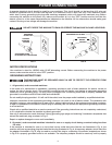
FIGURE 2
ASSEMBLY
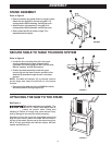
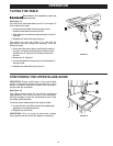
STAND ASSEMBLY
Refer to Figure 2
• Place top surface (A) upside down on a level surface.
Attach the four legs (B) to the top using M6 X 16
carriage bolts, M6 flat washers, and M6 hex nuts.
• Attach bottom rail supports (C) using M6 X 16
carriage bolts, M6 flat washers, and M6 hex nuts.
• Place rubber feet (D) on bottom of legs. Turn
assembled stand upright.
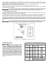
FIGURE 3
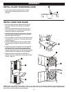
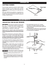
SECURE TABLE TO TABLE TRUNNION SYSTEM
Refer to Figure 3
• Locate the four mounting holes (A) in the upper
trunnion and attach the upper trunnion to the
underside of the table using four M8 X 20 hex bolts,
M6 lock washers, and M6 flat washers
• Position the table assembly so that the upper
trunnion fits into the lower trunnion and the trunion
feed bolt (B) extends through the slot in the lower
trunnion.
NOTE: The table tilt indicator (C) on the top trunnion
should align with table tilt scale (D) on the bottom
trunnion.
• Secure trunnion feed bolt using an 8MM flat washer
and black table tilt locking wing nut (E).
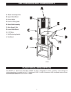
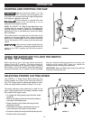
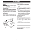
ATTACHING THE SAW TO THE STAND
See Figure 4.
This step requires two adults. The
DELTA
®
14" Steel Frame Band Saw is
heavy, be careful when lifting and
handling it! Failure to comply may cause serious injury
and/or damage to the machine and/or property!
Carefully lift the saw onto the assembled stand and
align the four holes in base of the saw with the holes in
the top of the stand. Secure saw to the stand using four
M8 X 20 hex head bolts with M8 flat washer, M8 lock
washer and M8 hex nut.
FIGURE 4