


8
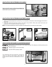
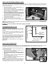
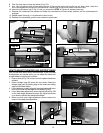
1. Attach the cutterhead adjustment handle (A) Fig. 6 to the shaft (B), with the flat on the shaft engaged with the flat in
the handle.
2. Fasten the cutterhead adjustment handle to the shaft using the M6 x 20mm star socket head screw and
lockwasher with the supplied cutterhead wrench (Fig. 7).
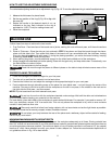
NOTE: The cutterhead adjustment handle is supplied with markings (C) Fig. 8 to make your cuts accurate.
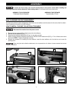
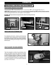
Use the supplied wrench to attach the cutterhead lock
handle (A) Fig. 5 to the shaft (B) with the M6 x 20mm star
socket head screw and lockwasher.
HOW TO ATTACH THE CUTTERHEAD LOCK HANDLE
Fig. 5
A
B
HOW TO ATTACH THE CUTTERHEAD ADJUSTMENT HANDLE
Fig. 6
Fig. 7
Fig. 8
B
A
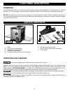
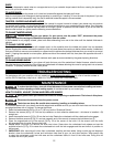
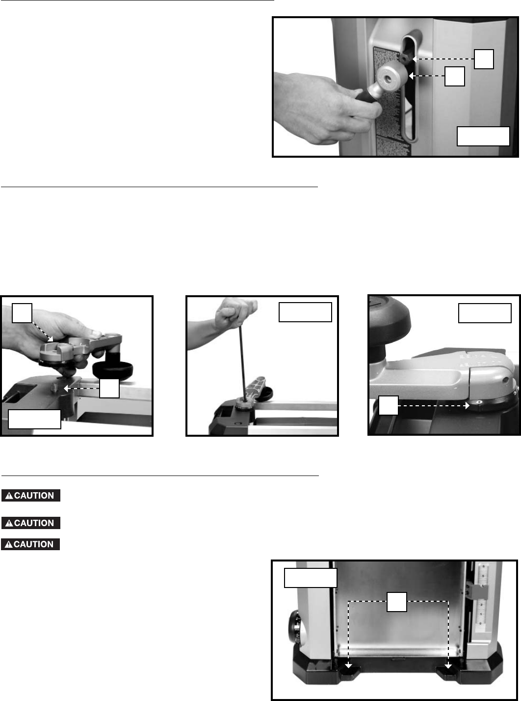
HOW TO FASTEN THE PLANER TO A SUPPORTING SURFACE
Four attachment holes are provided for mounting the
planer to a stand or work surface. These holes are
located under the infeed and outfeed tables as shown in
Fig. 9.
Before operation, secure the planer to the supporting surface. Four holes (two of which are shown at (A)
Fig. 9) are provided for this purpose.
Operate the planer on a flat, level surface.
C
Fig. 9
A
Use ONLY DELTA accessory stands.