


9
OPERATION
OPERATIONAL CONTROLS AND ADJUSTMENTS
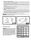
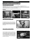
HOW TO START AND STOP THE PLANER
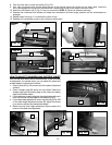
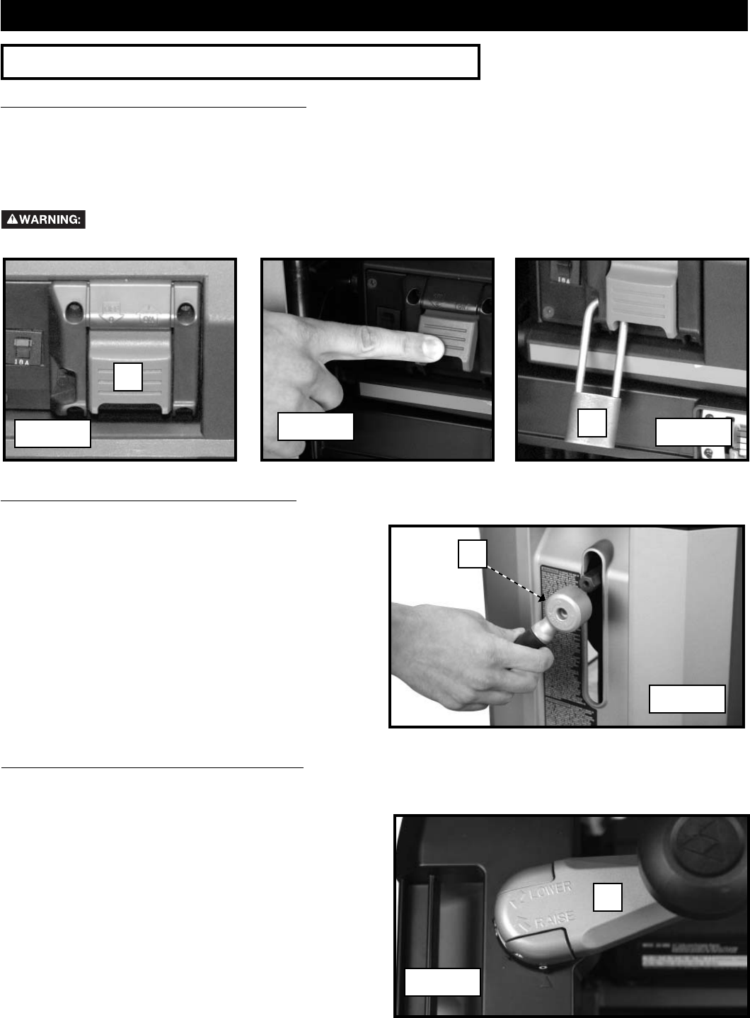
To turn the planer “ON”, lift the paddle (A) Fig. 10. To turn the tool “OFF”, push the paddle down (Fig. 11).
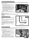
IMPORTANT: When the machine is not in use, the switch should be locked in the “OFF” position to prevent unauthor-
ized use. Place a padlock (B) Fig. 12 with a 1/4" (6.3 mm) diameter shackle through the hole on the left side of the switch
cover and through the hole in the switch paddle. Lock the padlock.
Ensure that the lock prevents the switch from being turned on.
Fig. 11
Fig. 12
B
A
Fig. 10
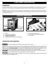
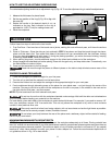
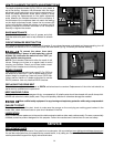
HOW TO USE THE CUTTERHEAD LOCK
The cutterhead lock (A) Fig. 13 helps to eliminate snipe
in the board that is being planed. Snipe can also be
eliminated by butting boards end to end and feeding
them through the planer. Long boards should always be
supported, when feeding them through the planer to help
eliminate snipe.
Fig. 13
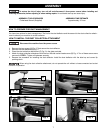
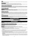
The head assembly contains the cutterhead, feed
rollers, chip deflector and motor. Raising and lowering
the head assembly controls the depth of cut. To adjust
the head assembly, rotate the cutterhead lock handle
(A) Fig. 13 counterclockwise to unlock the cutterhead.
Turn the cutterhead adjusting handle clockwise to raise
or counter-clockwise to lower the cutterhead. One
revolution of handle (A) Fig. 14 will move the cutterhead
up or down 1/16" (1.6 mm).
HOW TO ADJUST THE HEAD ASSEMBLY
Fig. 14
A
A