


5
CONNECTING DISC SANDER TO POWER SOURCE
POWER CONNECTIONS
A separate electrical circuit should be used for your tools. This circuit should not be less than #12 wire and
should be protected with a 20 Amp time lag fuse. If an extension cord is used, use only 3-wire extension
cords which have 3-prong grounding type plugs and 3-pole receptacles which accept the tool’s plug. Before
connecting the motor to the power line, make sure the switch is in the “OFF” position and be sure that the
electric current is of the same characteristics as indicated on the tool. All line connections should make good
contact. Running on low voltage will damage the motor.
MOTOR SPECIFICATIONS
Your disc sander is wired for 110-120 volt, 60 HZ alternating current. Before connecting the disc sander to
the power source, make sure the switch is in the “OFF” position. The motor provides a no-load speed of
1725 RPM.
GROUNDING INSTRUCTIONS
CAUTION: THIS TOOL MUST BE GROUNDED WHILE IN USE
TO PROTECT THE OPERATOR FROM ELECTRIC SHOCK.
In the event of a malfunction or breakdown, grounding
provides a path of least resistance for electric current to
reduce the risk of electric shock. This tool is equipped
with an electric cord having an equipment-grounding
conductor and a grounding plug. The plug must be
plugged into a matching outlet that is properly installed
and grounded in accordance with all local codes and
ordinances.
Do not modify the plug provided - if it will not fit the out-
let, have the proper outlet installed by a qualified electri-
cian.
Improper connection of the equipment-grounding con-
ductor can result in risk of electric shock. The conductor
with insulation having an outer surface that is green with
or without yellow stripes is the equipment-grounding
conductor. If repair or replacement of the electric cord or
plug is necessary, do not connect the equipment
grounding conductor to a live terminal.
Check with a qualified electrician or service personnel if
the grounding instructions are not completely under-
stood, or if in doubt as to whether the tool is properly
grounded.
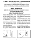
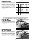
Use only 3-wire extension cords that have 3-prong
Fig. 6Fig. 5
GROUNDED OUTLET BOX
CURRENT
CARRYING
PRONGS
GROUNDING BLADE IS
LONGEST OF THE 3 BLADES
GROUNDED OUTLET BOX
GROUNDING MEANS
ADAPTER
grounding type plugs and 3-hole receptacles that accept
the tool's plug, as shown in Fig. 5.
Repair or replace damaged or worn cord immediately.
This tool is intended for use on a normal 120-volt circuit
and has a grounded plug that looks like the plug illus-
trated in Fig. 5.
If a properly grounded outlet is not available, a temporary
adapter, shown in Fig. 6, may be used for connecting the
3-prong grounding type plug to a 2-prong receptacle.
The temporary adapter should be used only until a prop-
erly grounded outlet can be installed by a qualified elec-
trician. The green colored rigid ear, lug, or the like
extending from the adapter must be connected to a per-
manent ground such as a properly grounded outlet box
cover. Whenever the adapter is used, it must be held in
place with a metal screw.
NOTE: In Canada, the use of a temporary adapter is
not permitted by the Canadian Electric Code.
CAUTION: IN ALL CASES, MAKE CERTAIN THE RE-
CEPTACLE IN QUESTION IS PROPERLY GROUNDED.
IF YOU ARE NOT SURE HAVE A CERTIFIED ELEC-
TRICIAN CHECK THE RECEPTACLE.