


7
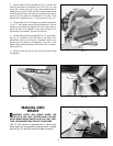
Fig. 10
Fig. 11
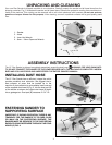
ADJUSTING MITER GAGE SLOT PARALLEL
WITH THE ABRASIVE DISC
MAKE CERTAIN MACHINE IS DISCONNECTED FROM POWER SOURCE BEFORE MAKING ADJUSTMENTS.
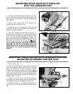
1. Check to see if the miter gage slot (G) Fig. 10, is par-
allel with the disc by placing a combination square in the
miter gage slot with one end of the square against the
disc as shown.
2. Using a pencil, make a mark on the abrasive disc
where the square contacts the disc.
3. Rotate the disc to the other end of the table and
check the distance using the square. If an adjustment is
necessary, proceed as follows:
4. Using the supplied wrenches (X) and (Y) Fig. 11,
loosen the four screws (F) Fig. 10, which secure the table
to the trunnions and adjust the table by moving it in or
out until the miter gage slot is parallel with the disc. Then
tighten four screws (F) Fig. 10. NOTE: When making this
adjustment, be sure the table locking handles, one of
which is shown at (A) Fig. 11, are tightened. WARN-
ING: TO AVOID TRAPPING THE WORK OR FINGERS
BETWEEN THE TABLE AND ABRASIVE DISC, THE
TABLE EDGE (Z) FIG. 10, SHOULD BE POSITIONED A
MAXIMUM OF 1/16" FROM THE ABRASIVE DISC, AS
SHOWN.
ADJUSTING TABLE SQUARE WITH ABRASIVE DISC AND
ADJUSTING 90 DEGREE POSITIVE STOP
MAKE CERTAIN MACHINE IS DISCONNECTED FROM POWER SOURCE BEFORE MAKING ADJUSTMENTS.
Fig. 12
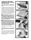
1. Set the table to zero.
2. Place an accurate square on the table with one end
of the square against the disc, as shown in Fig. 12. If the
table is not square to the disc, proceed as follows:
Loosen the table locking handles, one of which is shown
at (A) Fig. 12, located on each end of the table. NOTE:
Table locking handle (A) Fig. 12, is spring-loaded and can
be repositioned on the stud by pulling out the handle and
repositioning it on the nut.
3. Loosen locknut (B) Fig. 12, and adjust screw (C)
accordingly until table is square with the abrasive disc.
Then tighten table locking handles and locknut (B).
4. Loosen screw (D) Fig. 12, and adjust pointer (E) until
it points to the “0” mark on the scale. Then tighten screw
(D).
F
F
Z
X
Y
A
C
B
A
D
E
G