


9
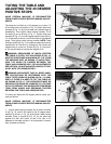
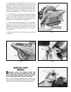
2. Loosen table locking handles (A) Fig. 17, and tilt the
table up as shown, to expose lock nut (F) Fig. 18, and
screw (G). Loosen lock nut (F) and return table to the 45
degree down position. With the table lock handles loose,
turn adjustment screw (G) using the supplied wrench (not
shown) until the table is 45 degrees to the disc. Then
tighten lock handles (A) Fig. 17, and locknut (F) Fig. 18.
3. Tilt the table to the 45 degree up position as shown
in Fig. 17, and tighten table locking handles (A). Place a
square on the table and against the disc and check to
see if the disc is 45 degrees to the table surface. If an
adjustment is necessary, proceed as follows:
4. Loosen table locking handles (A) Fig. 17, and locknut
(H) Fig. 19, located on the left side of the table. Turn
adjustment screw (J) using the supplied wrench (not
shown) until the table is 45 degrees to the disc. Then
tighten table locking handles and locknut (H) on adjust-
ment screw (J).
5. Adjust pointer (K) Fig. 19, so that the pointer reads
45 degrees.
Fig. 17
Fig. 18
Fig. 20
Fig. 19
MANUAL DISC
BRAKE
WARNING: APPLY THE BRAKE WHEN THE
SWITCH IS IN THE “OFF” POSITION ONLY. DO NOT
APPLY BRAKE WHILE SWITCH IS IN THE “ON” POSI-
TION, FOR DAMAGE MAY OCCUR TO MACHINE.
This 12" Disc Sander is equipped with a manual disc
brake which can be applied by pressing down on brake
lever (A) Fig. 20, after the switch has been turned off.
A
A
G
F
J
H
A
X
B