


8
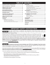
FIGURE 2
ASSEMBLY
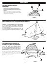
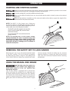
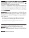
INSTALL BRAKE LEVER
ASSEMBLY
• Refer to Figure 2 and remove the 2 hex screws (A)
from the disc housing using the 2.5mm Allen wrench
supplied.
• Align the screw holes in the brake lever assembly (B)
with the holes in the disc housing and secure using the
hex screws removed in Step 1.
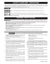
FIGURE 3
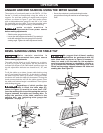
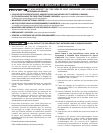
Important: If during operation there is any tendency
for the sander to tip over, slide or walk on the
supporting surface, the sander must be secured to
the supporting surface.
To secure the sander to the supporting surface, use
screws or bolts and nuts through the four holes (A) as
shown in Figure 3.
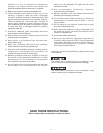
FIGURE 4
SECURE TOOL TO SUPPORTING SURFACE
A
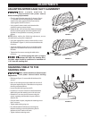
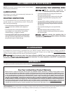
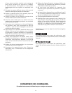
The 12" Disc Sander has an efficient, integral
fan which provides excellent dust collection. It
is recommended that the machine be attached
to a dust collector using the 2 1/4” dust port (A)
shown in Figure 4.
If a dust collector is not available, insert one end
of the supplied dust hose (B) into the dust port
and place the other end of the dust hose into a
garbage can or other receptacle.
CONNECT DUST HOSE TO
DUST COLLECTOR SYSTEM