10
ADJUSTMENTS
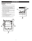
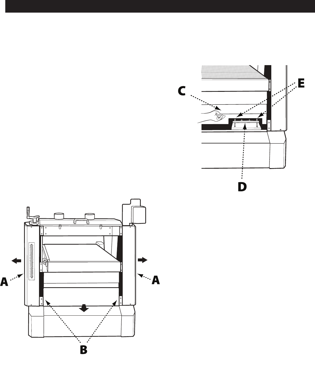
FIG. 6
TO ADJUST DRIVE BELT
TENSION
1. Remove the elevation cursor by unscrewing the
retaining screw.
2. Remove the eight Phillips head bolts and washers
securing the left and right side guards (A) to the
machine and remove the guards. See Fig. 6.
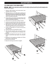
3. Use a 6mm Allen wrench to remove the four hex
cap bolts and washers securing the bottom guard
(B) to the machine. See Fig. 7.
4. Raise the telescoping panels (C) high enough to
expose the motor mount (D). See Fig. 7. Prop up
using a scrap block of wood.
5. Locate the two M12 nuts (E) that raise and lower the
motor. See Fig. 7.
6. To increase tension on the drive belts, loosen the
bottom nuts then tighten the top nuts.
7. Drop the telescoping panels back into place and
re-secure to the bottom guard.
8. Re-attach the side guards and elevation cursor.
FIG. 7


