


28
Fig. 83
Fig. 84
Fig. 85
Fig. 86
CUTTING
CROWN MOULDING
One of the unique features of your saw is the ease of
cutting crown moulding. The following is an example of
cutting both inside and outside corners on 52/38 degree
wall angle crown moulding. NOTE: When cutting 45
degree wall angle crown moulding the following
procedure for inside and outside corners is the same
with the exception that the bevel position will always be
at 30 degrees and the miter position will be 35-1/4
degrees to the right or left.
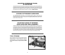
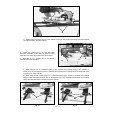
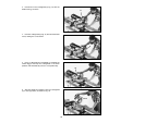
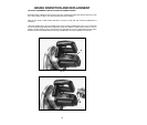
1. Set the rotating table to the 31.62 degree right miter
position, as shown in Fig. 83. A positive stop is provided
to set the rotating table at this angle quickly. Tilt the saw
blade to the 33.9 degree bevel position. An indicator is
provided on the bevel scale to find this angle quickly.
2. Place the crown moulding on the saw table with the
CEILING EDGE of the moulding against the fence, as
shown in Fig. 83, and make the cut. Note that we are
using the work clamp (A) Fig. 83, to hold the workpiece
firmly against the table. The piece of crown moulding
used for the outside corner will always be on the right
hand side of the blade, as shown at (B) Fig. 83. The piece
of crown moulding used for the inside corner will always
be on the left side of the blade, as shown at (C) Fig. 83.
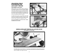
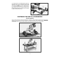
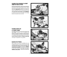
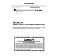
3. To make the matching halves of the inside and
outside corners, set the rotating table to the 31.62
degree left miter position, as shown in Fig. 84. A positive
stop is provided to set the rotating table at this angle
quickly. The saw blade is already tilted to the 33.9
degree bevel angle from the previous cut.
4. Place the crown moulding on the saw table with the
WALL EDGE of the crown moulding against the fence,
as shown in Fig. 84, and make the cut. Again, note that
we are using the work clamp (A) Fig. 84, to hold the
workpiece firmly against the table. The piece of crown
moulding used for the outside corner will always be on
the right side of the blade, as shown at (D) Fig. 84. The
piece of crown moulding used for the inside corner will
always be on the left side of the blade, as shown at (E)
Fig. 84.
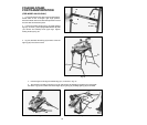
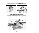
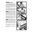
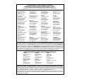
5. Fig. 85, illustrates the two outside corner pieces,
(B) being the piece cut at (B) Fig. 83; and (D) being the
piece cut at (D) Fig. 84.
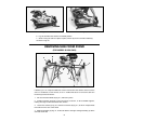
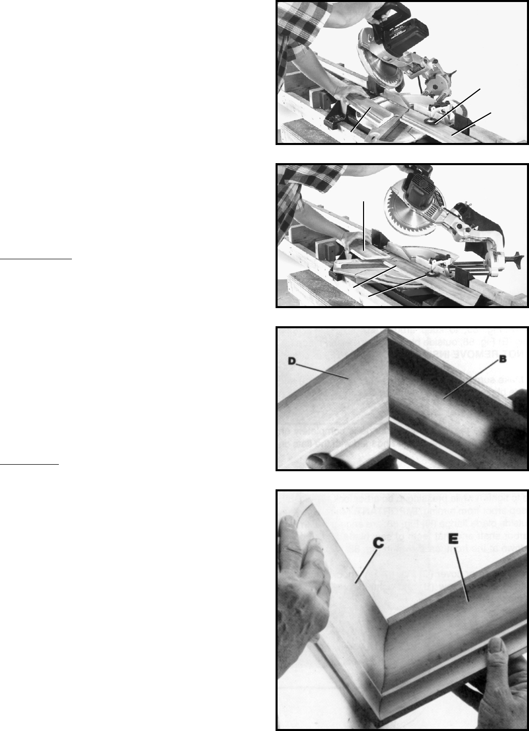
6. Fig. 86, illustrates the two inside corner pieces,
(C) being the piece cut at (C) Fig. 83; and (E) being the
piece cut at (E) Fig. 84.
C
A
B
E
D
A