


10
Fig. 14
Fig. 15
Fig. 16 Fig. 17
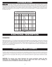
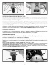
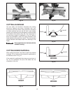
ROTATING TABLE FOR MITER CUTTING
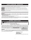
Your miter saw will cut any angle from 90° to 47°, right and left. Pull out on the lock handle (A) Fig. 14. Turn the lock
handle one or two turns counter-clockwise, depress the index lever (B), and move the table to the desired angle. Turn
the lock handle (A) Fig. 14 clockwise to tighten.
The miter saw is equipped with positive stops at the 0°, 22.5°, 31.62°, and 45° right and left positions. Loosen the lock
handle (A) Fig. 14, and move the table until the bottom of the index lever (B) engages into one of the positive stops (six
are shown at (C) Fig. 14). Tighten the lock handle.(A). To disengage the positive stop, loosen the lock handle and
depress the index lever (B).
Additionally, a triangle indicator and positive stop are provided on the miter scale at the 31.62° right and left miter
positions for cutting crown moulding. (Refer to the “CUTTING CROWN MOULDING” section of this manual).
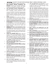
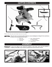
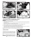
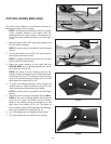
POINTER AND SCALE
An indicator (E) Fig. 15 shows the angle of cut. Each line on the scale (F) represents 1/2 degree. When you move the
indicator from one line to the next on the scale, you change the angle of cut by 1/2 degree.
ADJUSTING POINTER
To adjust the indicator (E) Fig. 15, loosen the screws (G), adjust the indicator (E), and tighten the screws.
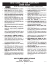
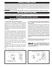
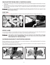
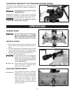
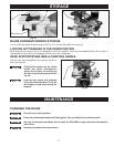
TILTING CUTTINGHEAD FOR BEVEL CUTTING
The cuttinghead of your saw can be tilted to cut any bevel angle from 90° to 45°, left or right. Push in and turn the lock
handle (A) Fig. 16 counter-clockwise. Tilt the cuttinghead to the desired angle and tighten the lock handle (A) Fig. 16
clockwise.
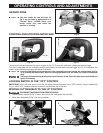
NOTE: To tilt the cuttinghead to the right, move the stop arm (B) Fig. 17 down.
Positive stops can rapidly position the saw blade at 90° and 45° to the table. Refer to the section of this manual entitled
“ADJUSTING 90° AND 45° BEVEL STOPS”. Use the pointer (C) Fig. 17 on the scale (D) to determine the angle.
Additionally, a triangle indicator is provided on the bevel scale at the 33.85° bevel angle for cutting crown moulding.
Refer to the “CUTTING CROWN MOULDING” section of this manual.
B
A
C
C
E
F
G
A
C
D
B