


11
Fig. 18
Fig. 19
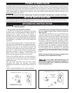
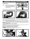
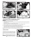
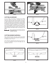
ADJUSTING 90° AND 45° DEGREE BEVEL STOPS
DISCONNECT MACHINE FROM POWER SOURCE.
1. Lock the machine in the “down” position.
2. Place one end of a square (A) Fig. 18 on the table and the other end against the blade. Verify that the blade is 90°
to the table (Fig. 18).
3. To adjust, push in and turn the lock handle (A) Fig 16 counter-clockwise. Loosen the nut (C) Fig. 19 and turn the
screw (D) until the blade is 90° to the table. Tighten the nut (C).
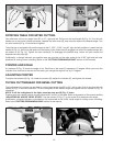
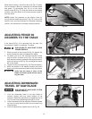
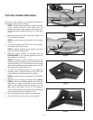
4. Raise the cuttinghead. Push in and turn the lock handle (J) Fig. 21 counter-clockwise to loosen.
5. Move the cuttinghead all the way to the left bevel position and tighten the lock handle.
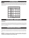
6. Use a combination square (A) Fig. 20 to verify that the blade is 45° to the table.
7. To adjust, push in and turn the lock handle (A) Fig 16 counter-clockwise. Loosen the nut (E) Fig. 21, and turn the
screw (F) until the blade is 45° to the table. Tighten the nut (E). Tighten the lock handle.
8. Adjust the right 45° bevel stop in the same manner with screw (G) and nut (H) Fig. 21.
NOTE: Move the stop arm (B) Fig. 17 down when changing the bevel angle to the right.
A
C
D
ALWAYS tighten the bevel lock handle (A) FIG. 16 securely before operating the saw.
Fig. 20
Fig. 21
A
E
F
G
H
J
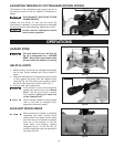
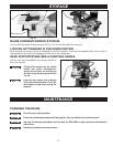
The sliding fence (A) Fig. 22 provides support of large
workpieces. Set it as close as possible to the saw blade.
When miter cutting at 0° bevel (blade 90° to the table),
the fence (A) should be all the way toward the blade (Fig.
22).
Verify that the fence is clear of the
blade and blade guard, and that it is
locked in place before operating the
saw.
SLIDING FENCE
Fig. 22
A
B
C