


12
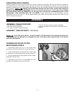
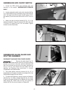
ASSEMBLING GPE ON/OFF SWITCH
1. Locate the GPE switch and hardware that was
removed in the section “ASSEMBLING EXTENSION
WING.”
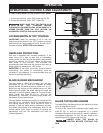
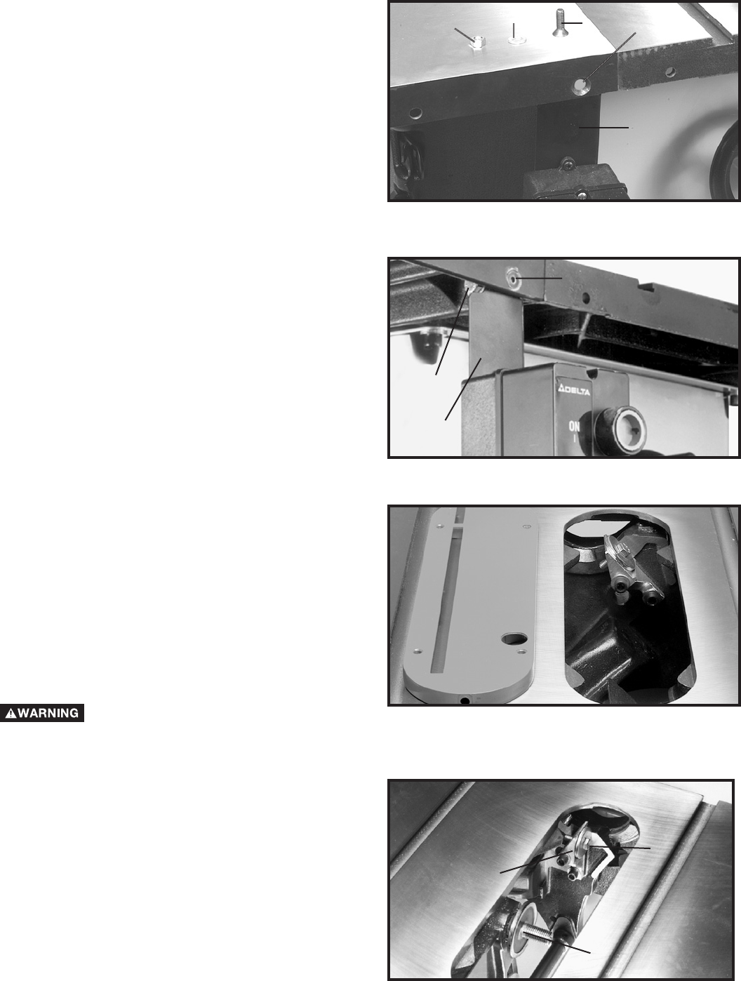
2. Loosely assemble switch and switch bracket (A) Fig.
12, to the inside front lip of extension wing. Insert a 5/16-
18x1" flat head screw (D) through hole (G), place a 5/16"
flat washer (E) on screw and secure with a 5/16" hex nut
(F).
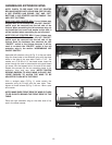
3. Attach the side of switch bracket (A) Fig. 13, to the
inside of extension wing at the front of the saw using the
7/16-20x1-1/4" screw (C) and 7/16" flat washer. Tighten
screws (C) and (D) securely.
Fig. 12
Fig. 13
D
C
A
Fig. 14
Fig. 15
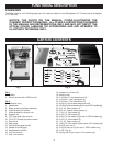
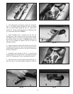
ASSEMBLING BLADE GUARD AND
SPLITTER ASSEMBLY
DISCONNECT MACHINE FROM POWER SOURCE.
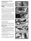
1. Remove the table insert Fig. 14.
Raise the saw arbor, by turning the locking
handle on the front of the saw, counter clockwise and
then turn the wheel on the front of the saw clockwise as
far as it will go, and remove the saw blade from the
machine by following the instructions in section
“CHANGING THE SAW BLADE”.
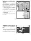
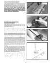
2. The inside splitter mounting bracket (A) Fig. 15, is
assembled to the inside of the saw and aligned with the
inside blade flange (B) at the factory.
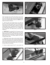
3. To check the alignment, remove screw and fastener
plate (C) Fig. 15. Using a straight edge (D) Fig. 16, check
to see if the splitter bracket (A) is aligned with the inside
blade flange (B). Check both the top and bottom of
bracket (A) with the top and bottom of flange (B).
A
B
C
A
D
E
F
G