


11
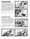
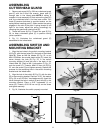
ASSEMBLING
CUTTERHEAD GUARD
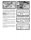
1. Remove set screw (A) Fig. 20 from cutterhead guard
post (F) with the 2.5mm hex wrench. Insert post (F)
through hole in the infeed table. NOTE: A spring is
supplied in knob assembly (E) that returns the guard (C)
over the cutterhead after a cut has been made. Turn
knob (E) counter-clockwise to provide tension on the
spring before inserting post (F). Make certain the spring
engages in the slot of the post. If spring tension is too
tight or too loose, adjust the spring accordingly by
removing the guard and rotating knob (E).
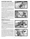
2. Thread set screw (A) Fig. 21 back into post (F) Fig.
20, to keep cutterhead guard (C) in position during
jointer operation.
3. Fig. 21, illustrates the cutterhead guard (C)
assembled to the infeed table.
Fig. 20
A
C
D
E
Fig. 21
A
C
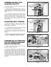
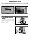
ASSEMBLING SWITCH AND
MOUNTING BRACKET
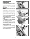
1. Align the two holes in the switch mounting bracket
(A) Fig 22, with the two holes (D) in the back of the infeed
table (B). Place an M8 flat washer (E) Fig. 22, on an
M8x1.25x30mm hex socket head screw (C). Insert the
screw through the hole (D) Fig. 22, in the switch
mounting bracket (A) and the hole in the back of the
infeed table (B). Place a M8.1 lockwasher (F) Fig. 22,
onto the screw (C). Thread a M8x1.25 hex nut (G) Fig.
22, onto the screw (C) and tighten securely. Repeat this
process for the remaining hole in the switch mounting
bracket and the infeed table.
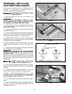
2. Align the hole in the switch (E) Fig. 23, with the hole
(G) in the mounting bracket. Place an 11/32" flat washer
(I) Fig. 23, on a 5/16-18x1" hex head screw (H). Insert the
screw through the hole in switch (E) and hole (G) in the
mounting bracket. Place a 5/16" lockwasher (J) on
screw (H). Thread a 5/16-18 hex nut (K) on the screw
and tighten securely.
3. Fig. 24, illustrates the switch properly mounted.
Fig. 22
A
B
C
D
Fig. 23
Fig. 24
A
G
E
H
E
F
G
I
J
K
F