


9
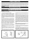
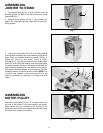
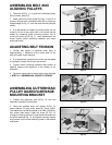
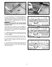
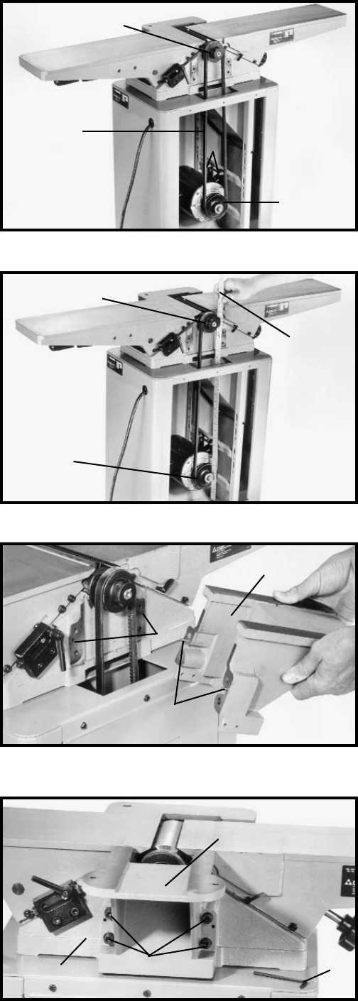
ASSEMBLING BELT AND
ALIGNING PULLEYS
1. Place belt (A) Fig. 11, in groove of cutterhead pulley
(B) and motor pulley (C).
2. Make certain the motor pulley (C) Figs. 11 and 12, is
properly aligned with cutterhead pulley (B) by placing a
straight edge (D) Fig. 12, onto the face of each pulley as
shown.
3. If an adjustment is needed, the motor pulley can be
moved in or out on the motor shaft, or the motor can be
shifted by loosening motor mounting screws, two of
which are shown at (E) Fig. 11. After adjustments are
made, tighten motor mounting hardware and motor
pulley set screw.
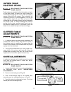
ADJUSTING BELT TENSION
1. Correct belt tension is obtained when there is
approximately 1" deflection at the center span of the
belt using light finger pressure.
2. If an adjustment is required, the motor can be raised
or lowered to obtain the correct belt tension.
3. Tighten motor mounting hardware after tension is
applied, making sure alignment of the pulleys is not
disturbed.
4. Re-attach back panel of stand which was removed
in STEP 2 of “ASSEMBLING JOINTER TO STAND”.
Fig. 11
E
C
A
B
B
C
D
Fig. 12
Fig. 14
Fig. 13
A
B
C
G
E
D
C
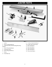
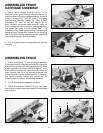
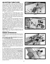
ASSEMBLING CUTTERHEAD
PULLEY GUARD/CARRIAGE
MOUNTING BRACKET
1. Position two alignment pins (A) Fig. 13, with two
alignment holes (B) in jointer base.
2. Using the supplied 6mm hex wrench (E) Fig. 14,
fasten bracket (C) onto jointer base (G). Place a M8.1
lockwasher then an M8 flat washer on an M8x1.25x55mm
hex socket head screw. Insert the screw (D) Fig. 14,
through the hole in bracket (C), and thread the screw into
the jointer base (B) Fig. 13, and tighten securely. Repeat
this process for the three remaining holes in the bracket
and jointer.